The following example of the EXNET Ring Configure message shows the first message from the sequence:
|
BYTE |
Field Description |
Value and Indication |
|---|---|---|
|
0 |
0xFE |
|
|
1, 2 |
0x000c |
|
|
3, 4 |
Message Type |
0x0074 (EXNET Ring Configure) |
|
5 |
Reserved |
0x00 |
|
6 |
Sequence Number |
0xSN |
|
7 |
Logical Node ID |
0x01 (Logical Node 1) |
|
8 |
Address Method |
0x00 (Single Entity) |
|
9 |
Number of Address Elements |
0x01 |
|
10 |
AIB Type |
0x1a (Logical Ring) |
|
11 |
Address Data Length |
0x01 |
|
12 |
Address Data[0] Logical Ring ID |
0x01 (Logical Ring ID 1) |
|
13 |
Entity |
0x02 (Con Transmit Mode) |
|
14 |
Data[0] Transmit Mode |
0x01 (Transmit/Receive) |
|
15 |
Checksum |
|
After you finish all CSP configuration, bring the ring in service, using the Service State Configure message. You must send this message to only one node of all the nodes on a given EXNET ring.
Each node informs all of the other nodes of its Logical Node ID. Each node stores this information for API messaging and PCM data routing. The messaging among nodes during ring setup is performed over the same Ethernet link as the host-to-nodes communication link.
When all nodes are assigned and established on the ring, the ring begins a sequence to come in service. The host receives Ring Status Report messages as the ring transitions through states of Connected, Initializing, and In Service.
If the ring fails, it is taken out of service automatically. Until the ring is brought back in service, no connections can be made among nodes.
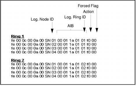
Example: The sequence shown in Service State Configure - Bring Rings In Service brings Ring 1 and Ring 2 in service.
You should receive a sequence of Ring Status Report messages from each node, indicating that the ring is initializing, connected, and in service and that the EXNET ports are in Normal node. The Signal Detect and Fault Detect LEDs on the EXNET-ONE cards should be green.
Figure 10-4 Service State Configure - Bring Rings In Service