You are here: SwitchKit CSA User’s Guide > 4 Configuring Signaling Cards > Configuring the SS7 Card

This procedure describes configuring an SS7 card.
Before you begin
The signaling method for a T1 and/or E1 spans must be set to: clear channel. You must obtain the following:
• SS7 user part licenses
• Originating, adjacent and destination point codes
• A CCS I/O card is required to support redundancy, SS7 over a CSP ring or SCCP/TCAP.
• An IP address is required for SCCP/TCAP configuration on each SS7 card.
• An Ethernet connection is required for each SS7 card over a CSP ring.
• Before configuring SS7 links, you must first assign spans on T-ONE, E-ONE, J-ONE and Multi-Protocol I/O cards.
You must have a node view window open in configuration mode. If you set up redundant SS7 cards place them in adjacent card slots. You may configure four stacks per SS7 card; each stack has an individual point code (OPC).
Important! When using SS7 PQ cards in either a single node or a multi-node system you may configure a total of 3000 physical and virtual CICs, if both ISUP and SCCP/TCAP are to be configured for this system.
Information Source
Please refer to the SS7 information contained in the API Reference and the Developer’s Guide: Common Channel Signaling.
Configuring the SS7 Card
The following steps guide you through the initial sequence of configuring an SS7 Card. If your card is already configured and you want to change parts of that configuration, please look for the appropriate information in this procedure. To modify any of these SS7 configuration settings, click on the entity you want to modify.
1 To invoke the SS7 Card Configuration dialog box, do one of the following:
• Double-click the SS7 card in the node view window.
• Right-click the SS7 card in the node view window and select SS7 Configuration from the drop-down list.
• Select the SS7 card, go to the Configuration menu and select Card®SS7 Configuration.
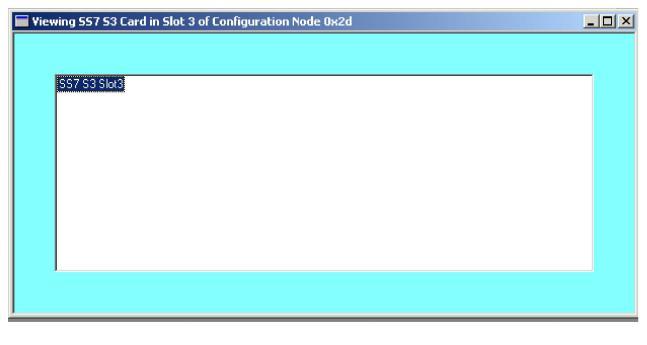
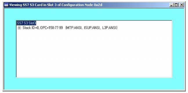
The Viewing SS7... dialog box opens. See the next screen shot.
2 Next, you must configure the SS7 Stack.
To invoke the SS7 Stack configuration dialog box, do one of the following:
• Right-click the SS7 entry in the view and select SS7 Stack Configuration from the menu.
• Select the SS7 entry in the view and go to the Configuration menu. Select SS7®SS7 Stack Configuration.
This opens the Configure SS7 Stack dialog box:
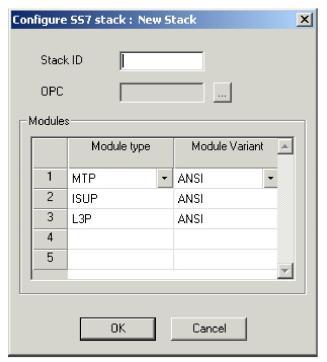
3 Enter the Stack ID. The valid IDs are 0 to 3.
4 Select the Module Type and Module Variant from the drop-down lists for the Modules. The Module Variant must be the same for all modules in one Stack ID.
5 Click the button: ![]() When ANSI module variants are selected, the OPC (ANSI) dialog box opens. When other module variants are selected, the OPC dialog box for the selected variant opens.
When ANSI module variants are selected, the OPC (ANSI) dialog box opens. When other module variants are selected, the OPC dialog box for the selected variant opens.
6 Enter the Originating Point Code (OPC). The OPC must be a numeric value. For example, an originating point code would be entered as 158 77 99. For more details, see the section: "SS7 Point Codes" in the Basics of SS7, Chapter 2, Developer’s Guide: Common Channel Signaling.
7 Click OK.
8 Click OK to close the dialog box. The SS7 Card view shows the stack information. The configuration data shown in the screen on the next page is example data.
9 You must now configure the SS7 Link Set.
To invoke the SS7 Link Set configuration dialog box, do one of the following:
• Right-click the SS7 Stack entry in the view and select SS7 Link Set Configuration from the menu.
• Select the SS7 Stack entry in the view and go to the Configuration menu. Select SS7®SS7 Link Set Configuration.
This opens the Configure SS7 Link Set dialog box:
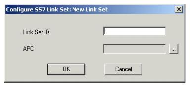
10 Enter the Link Set ID. The valid IDs are 0 to 32.
11 Click the button: ![]() The APC dialog box opens.
The APC dialog box opens.
12 Enter the Adjacent Point Code (APC). The APC must be a numeric value and be different from the OPC. For example, an adjacent point code would be entered as 111 251 241. For more details, see the section: "SS7 Point Codes" in the Basics of SS7, Chapter 2, Developer’s Guide: Common Channel Signaling.
13 Click OK.
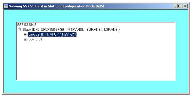
14 Click OK to close the dialog box. The SS7 Card view shows the stack information. The configuration data shown in the next screen shot is example data.
15 Next, you must configure the SS7 Link.
Before configuring SS7 links, you must first assign spans on T-ONE, E-ONE, J-ONE and Multi-Protocol I/O cards.
To invoke the SS7 Link configuration dialog box, do one of the following:
• Right-click the Link Set entry in the view and select SS7 Link Configuration from the menu.
• Select the Link Set entry in the view and go to the Configuration menu. Select SS7®SS7 Link Configuration.
This opens the Configure SS7 Link dialog box.
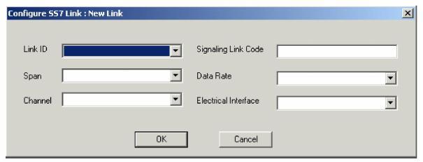
16 Specify the Link ID by selecting a value from the drop-down list.
17 Specify the Span by selecting a value from the drop-down list.
18 Specify the Channel by selecting a value from the drop-down list.
19 Enter the Signaling Link Code, valid range 0 to 15. The Signaling Link Code (SLC) must be the same on both ends of the link.
20 Specify the Data Rate by selecting a value from the drop-down list.
21 Specify the Electrical Interface by selecting a value from the drop-down list.
22 Click OK.
23 You must now configure the SS7 Route.
To invoke the SS7 Route Configuration dialog box, do one of the following:
• Right-click the Link Set entry in the view and select SS7 Route Configuration from the menu.
• Select the Link Set entry in the view and go to the Configuration menu. Select SS7®SS7 Route Configuration.
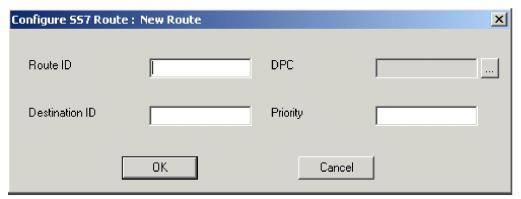
This opens the Configure SS7 Route dialog box. See the next screen shot.
f
24 Enter the Route ID.
25 Enter the Destination ID.
26 Click the button: ![]() The DPC dialog box opens.
The DPC dialog box opens.
27 Enter the Destination Point Code (DPC). The DPC can be the same as the APC. For example, a destination point code would be entered as 101 205 241. For more details, see the section: "SS7 Point Codes" in the Basics of SS7, Chapter 2, Developer’s Guide: Common Channel Signaling.
28 Click OK.
29 Enter the Priority, valid range 0 to 35.
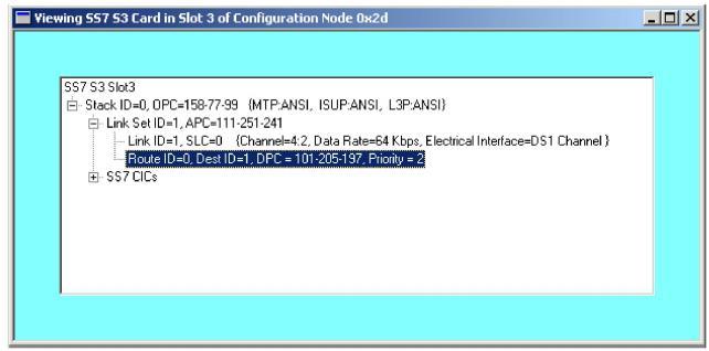
30 Click OK to close the dialog box. In the SS7 Card view you now see the SS7 Stack, Link Set, Link, and Route information. The configuration shown in the next screen shot uses example data.
31 Next you must configure either:
• SS7 Circuit Identification Code (CIC). See Step To invoke the SS7 CIC Configuration dialog box, do one of the following:.
• SCCP/TCAP. See Configuring SCCP/TCAP on an SS7 card.
32 To invoke the SS7 CIC Configuration dialog box, do one of the following:
• Right-click the SS7 CICs entry in the view and select SS7 CIC Configuration from the menu.
• Select the SS7 CICs entry in the view and go to the Configuration menu. Select SS7®SS7 CIC Configuration.
The Configure SS7 CIC dialog box opens. See the next screen shot.
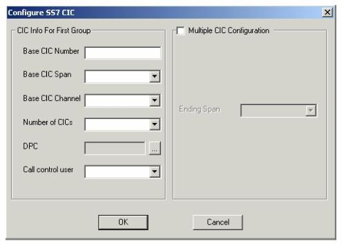
33 Enter the Base CIC Number.
34 Select the Base CIC Span from the drop-down list.
35 Select the Base CIC Channel from the drop-down list.
36 Select the Number of CICs from the drop-down list.
37 Enter the DPC, the same as in Step Enter the Destination Point Code (DPC). The DPC can be the same as the APC. For example, a destination point code would be entered as 101 205 241. For more details, see the section: "SS7 Point Codes" in the Basics of SS7, Chapter 2, Developer’s Guide: Common Channel Signaling..
38 Select the Call Control User from the drop-down list.
39 You can click OK to close the dialog box to create one base CIC. Or, if you want to create multiple CICs in one step, do the following:
• Select Multiple CIC Configuration
• Then, select the Ending Span from the drop-down list.
The configuration shown in the next screen shot uses example data.
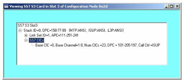
40 Click OK to close the dialog box. You have now created all the necessary SS7 Configuration information.

SS7 Message Formats
After you finished the SS7 stack configuration you are able to Configure SS7 Message Formats, please refer to the Configuring SS7 ISUP/TUP Message Formats procedure for instructions.
Note
Configuration changes are not sent to the CSP until you select the menu: Configure® Configure Through SwitchMgr® Send Only Modified Configuration to Switch.