Home > CG 6060 switching > PRI mode switching
This topic contains the following PRI mode switching information:
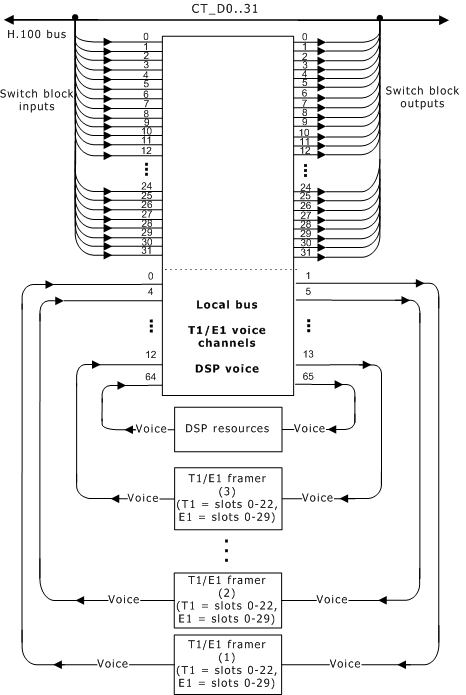
The following illustration shows the CG 6060 switching model in PRI mode:

The following tables list the specific use of each stream in the CG 6060 PRI switch model:
H.100 bus |
Streams 0..31, timeslots 0..127 (Streams clocked at 8 MHz) |
Trunk voice information (T1 trunks) |
Trunk 1: Streams 0 and 1 Trunk 2: Streams 4 and 5 Trunk 3: Streams 8 and 9 Trunk 4: Streams 12 and 13 |
timeslots 0..22 timeslots 0..22 timeslots 0..22 timeslots 0..22 |
Trunk voice information (E1 trunks) |
Trunk 1: Streams 0 and 1 Trunk 2: Streams 4 and 5 Trunk 3: Streams 8 and 9 Trunk 4: Streams 12 and 13 |
timeslots 0..29 timeslots 0..29 timeslots 0..29 timeslots 0..29 |
DSP voice information (T1 and E1 trunks) |
Streams 64 and 65, timeslots 0.. up to 899 |
|
In PRI mode, the D channel signaling is automatically terminated by an internal HDLC controller.
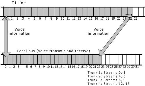
If NetworkInterface.T1E1[x].SignalingType = PRI, signaling information is routed to accommodate the T1 ISDN common channel signaling configuration, where voice information is transmitted in the first 23 channels. Each voice channel on the T1 trunk is placed in a corresponding timeslot on the local bus in the following streams:

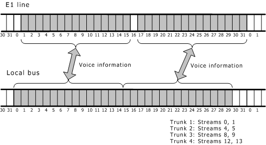
Regardless of the NetworkInterface.T1E1[x].SignalingType setting, the CG 6060 board routes the voice information by assigning E1 timeslots 1 through 15 to the local bus timeslots 0..14. E1 timeslots 17 through 31 are assigned to the local bus timeslots 15..29. Timeslot 0 on the E1 line carries framing data.
The following illustration shows how voice channel data is assigned to timeslots:

If NetworkInterface.T1E1[x].SignalingType = PRI, signaling information is routed differently to accommodate an ISDN common channel signaling configuration, where CCS signaling packets are transmitted in the D channel.
In PRI mode, the trunk signaling streams are not used. In this case, each trunk signaling stream has zero timeslots.
On CG 6060 boards, framer signaling is hard wired to internal HDLCs when the board runs in PRI mode. Refer to the PRI mode switch model. HDLC signaling is automatically terminated by an internal HDLC.
If a board is configured for standalone operation (Clocking.HBus.ClockMode = STANDALONE), the DSPs and trunks are connected as shown in the following table.
Note: The SwitchConnections keyword can override this setting.
The exact settings for CG 6060 boards configured as T1 or E1 depend upon the NetworkInterface.T1E1[x].SignalingType keyword setting.
The following table shows the default routing for CG 6060 boards in PRI mode:
Trunk type |
Full duplex connection between trunk voice information and the DSP resources... |
|
|---|---|---|
T1 |
Trunk 1: 0:0..22 => 65:0..22 Trunk 2: 4:0..22 => 65:24..46 Trunk 3: 8:0..22 => 65:48..70 Trunk 4: 12:0..22 => 65:72..94 |
64:0..22 => 1:0..22 64:24..46 => 5:0..22 64:48..70 => 9:0..22 64:72..94 => 13:0..22 |
E1 |
Trunk 1: 0:0..29 => 65:0..29 Trunk 2: 4:0..29 => 65:30..59 Trunk 3: 8:0..29 => 65:60..89 Trunk 4: 12:0..29 => 65:90..119 |
64:0..29 => 1:0..29 64:30..59 => 5:0..29 64:60..89 => 9:0..29 64:90..119 => 13:0..29 |
On CG 6060 boards, the framer signaling is hard wired to internal HDLCs when the board runs in PRI mode.
Note: The CG 6060 board does not allow signaling streams to be connected to the CT bus.