Home > Trunk MIB overview > Trunk MIB representation
This topic describes the NMS Communications implementation of the Trunk MIB (RFC 2495). The organization of the tree, detailed descriptions of the nodes, and the available functions are also provided. Compliance to the Trunk MIB is also detailed.
All the boards in a chassis are represented as one managed node. A numerical index represents each trunk. This number is generated by sequentially numbering the trunks on all the boards.
RFC 2495 defines the near end and far end of each DS1 interface. The near end is the interface on the board that the agent is monitoring. The far end is the remote end of the trunk connected to that interface. Support is defined for the near end.
The RFC 2495 MIB defines the following groups:
|
Group |
Description |
|---|---|
|
DS1 near end group |
Contains configuration information about the DS1 interfaces and statistics collected from the near end interface. |
|
DS1 far end group |
Optional and not supported. |
|
Fractional table |
Optional and not supported. |
|
Channel mapping table |
Optional and not supported. |
|
Trap group |
Enables a trap to be sent when the status of the interface changes. |
RFC 1573 defines an ifTable for all the interfaces in the system as part of MIB2. The NMS SNMP agent cannot access the ifTable. Therefore some portions of the RFC 2495 MIB are not supported.
The dsx1ChannelMappingTable is also not available.
The DS1 near end group consists of the following tables:
|
Table |
Contains... |
|---|---|
|
Information about each DS1 interface such as the number of bits per second that the circuit can reasonably carry, variety of zero code suppression, and the vendor's circuit identifier. |
|
|
Statistics for the current 15-minute interval. |
|
|
Statistics collected by each DS1 interface for the last 24 hours of operation. The past 24 hours are broken into 96 15-minute intervals. After 24 hours, the next interval pushes the oldest one out of the table. |
|
|
Cumulative sum of the statistics for the period of time since this MIB was first started. Each field in this table contains the sum of the fields in the Current table for a particular interface. |
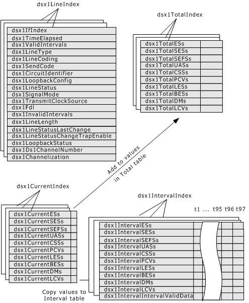
The information in the Current table refreshes continuously. Every 15 minutes, the current table's contents are copied to the Interval table and the sum of values from the Current table is added to the Total table. The Total table never resets, so the values are sums from the first time you started the DTM agent.
The following illustration shows the relationship between the DS1 tables:

The illustration shows a logical view of the tables for three DS1 interfaces. The Configuration table has an entry for each DS1 interface, which is identified by dsx1LineIndex. This index corresponds to the index in the other tables, such that all table entries with the same index number are for the same DS1 interface. Three DS1 interfaces are represented, so each table has three pages. An entry object starts each column of values.
Every 15 minutes, the values in the Current table are copied to the next available time slot (for example, if t1 was filled 15 minutes ago, t2 is filled next) in the Interval table. The Current table values are added to the values in the Total table and continue to add up until the agent is restarted.
If the Interval table is full when a new timeslot is added to the table, the last time slot (t97) is discarded and the rest of the timeslots slide forward to make room for the new t1 timeslot.
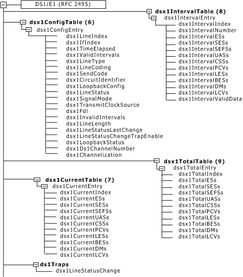
The following illustration shows a tree view of the sequence of objects in the Trunk MIB:
