You are here: CSP Developer’s Guide: Common Channel Signaling > 4 SS7 Call Control for ISUP > ANSI ISUP Continuity

Introduction
This section explains the various aspects of ISUP continuity procedure for ANSI as implemented in the CSP. It includes:
• message flows between exchanges
• the involvement of host application in each scenario
• the timer involved and various configurable parameters
ISUP Continuity Check
Continuity check is performed to verify the integrity of the voice circuit between two exchanges before use of the circuit. An exchange can initiate a continuity check on a circuit intended to be used for a call by one of the following ways:
1. Sending an IAM (Initial Address Message) message with a Nature of Connection parameter having continuity check indicator bits set to "required on this circuit".
2. Sending a CCR (Continuity Check Request) on the circuit which fails the initial continuity test mentioned in 1.
3. Sending a CRM (Circuit Reservation Message) with the Nature of Connection parameter having continuity check indicator set to "required on this circuit"
The exchange does the following when it receives these messages:
1. Does a "loopback" on the circuit under test.
2. Starts timer T8 (15 s). Expiration of T8 timer causes the connection to be cleared with cause 41.
The originating Exchange tests the continuity of the circuit by, attaching a transceiver on the circuit under test, sending a tone and verifying that the same tone is received via the loop back.
The continuity test result is propagated to the destination exchange by an ISUP message called COT with the continuity indicator mandatory parameter set to "failed" or "passed".
Example - COT Success
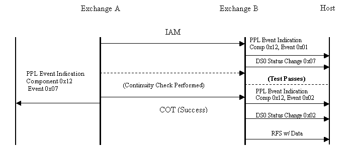
The call flow below shows IAM from Exchange A with nature of connection parameter set to continuity required on this circuit followed by a COT (successful) message.
Exchange A’s CPC component (0x12) sends a PPL event indication of Continuity Check Outgoing Success (0x07) to the host.
At the receiving side, the host receives a PPL event indication of COT indication in IAM (event 0x02) followed by a DS0 Status Change of 0x07 (Maintenance Loopback), Exchange B’s CPC component (0x12) starts timer T8 and goes into wait for COT state after receiving IAM with nature of connection parameter set to continuity required on this circuit. On receiving the COT (Success) message, the timer T8 is stopped, and the host is informed by sending a PPL event indication of COT success (event 0x02) followed by a DS0 Status Change of 0x02 (In-service) and subsequently the RFS with Data.
Components Involved
CPC (0x12)
Timers Involved:
T8: Wait for COT message
Example - COT Failure
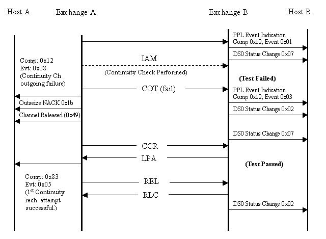
The call flow below shows the IAM from Exchange A with nature of connection parameter set to continuity required on this circuit followed by a COT (fail) message.
Exchange A’s CPC component (0x12) sends a PPL event indication of Continuity Check Outgoing Failure (0x08) to the host and starts the CRO (Continuity Recheck Outgoing) procedure. The host will receive an Outseize Control NACK of 0x1b to its Outseize Control message, and subsequently a Channel Released message (0x49).
Important! The host should not consider this channel idle. Attempts to send subsequent Outseize Control messages will result in a 0x0a NACK (Continuity Recheck Running)
The CRO component (0x83) takes over from this point and automatically sends a CCR (Continuity Check Required) message to Exchange B.
This time the continuity test passed and the CCR is followed by REL message. The host (Host A) is informed of this by a PPL event indication of 1st Continuity Recheck attempt successful (0x05) from the CRO component (0x83).
On the inbound leg, Exchange B’s CPC component sends a PPL event indication of COT failure (0x03) to the host on receiving the COT (failed) message and starts the CRI (Continuity Recheck Incoming) procedure. The CRI component (0x15) takes over from this point. The CRI component, upon receiving the CCR message, applies a loopback on the circuit sends LPA (Loopback Acknowledgement) and waits for REL or COT message.
A REL message implies that the continuity check was successful and the circuit is put in idle state. A COT message implies that the COT failed. This causes the CRI component to go in wait for CCR state and the whole procedure is repeated.
Components involved:
• CPC(0x12)
• CRI(0x15)
• CRO(0x83)
Timers involved:
• CRI:
• T-CCR: Wait for CCR message
• T-34: Wait for COT report or REL message
• T-27: Wait for continuity Recheck (second CCR message)
• CPC:
• T8: Wait for COT message
• CRO:
• T25: Wait before starting the repeat continuity check after continuity failed
Notes:
• Upon a successful continuity test after CCR message, the originating exchange does not send a COT (pass) message but a release message.
• A Call Progress Tone (CPT) transmitter and a Call Progress Analysis (CPA) receiver of appropriate PCM encoding are required in order to perform outgoing continuity checks.
• Host B is intimated about the incoming call before or after the COT result depending upon the value of config byte 0x09 of the CPC component 0x12. See Continuity check on previous circuit for more information.
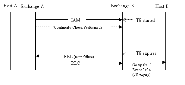
Example - T8 Expiration
When, due to some reason, Exchange A fails to send a COT report to Exchange B within T8 seconds (default value 15 seconds), Exchange B sends a REL message to Exchange A with a cause of temporary failure as shown in the call flow below.
Continuity Check Request (CCR)
A COT fail message followed by CCR messages (after T25 of the COT-fail) is sent to Exchange B in case the continuity test fails after the first CCR message. CCR message is sent repeatedly in such cases (repeated COT failures) after every T26 seconds (timer value).
The Repeated continuity check will only be finished when continuity is detected (that is, continuity test passes) or manual intervention occurs.
Example - Repeated COT Failure
As shown in the call flow below, in the case of repeated failures the CRO component repeatedly sends CCR to the destination exchange. The first recheck result is indicated to the host by the PPL event indication of "1st Continuity Recheck attempt failure" (0x03) from the CRO component (0x83) and the subsequent failures are indicated by "Continuity Recheck attempt failure" (0x04).
At Exchange A, the host will receive an Outseize Control NACK of 0x1b to its Outseize Control message (0x002C), and subsequently a Channel Released (0x0049) message.
The host should not consider this channel idle. Attempts to send subsequent Outseize Control messages will result in a 0x0a NACK (Continuity Recheck Running). Upon reception of "Continuity Recheck attempt failure" (0x04) indication, the host may choose to stop the Recheck procedures by sending a "Manual Stop" PPL Event Request of 0x40 to component L3PCIC (0x000f).
Exchange A will send a REL message to clear the circuit, and the host will receive a PPL Event Request of 0x01 "Subsequent Continuity Recheck attempt successful" (0x01) from component 0x0083 (CRO). This request is slightly misleading since the recheck was technically not successful in terms of a check tone. The host must recognize that this event is in response to its request to stop the proceedings.
At Exchange B, a success in one of the subsequent attempts is informed by a PPL event indication of "Subsequent Continuity Recheck attempt successful" (0x01). During this time, the inbound circuit will be placed in a Maintenance Loopback state indicated by a DS0 Status Change of 0x07. A DS0 Status Change of 0x02 will notify the host at Exchange B of the completion of continuity checks.
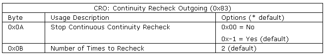
To avoid getting into an infinite loop in case of repeated failures, the CSP gives an option of limiting the continuity checks.
The default behavior of the CSP is to initiate a CCR message after a failed COT and try it four times in case the subsequent continuity checks fail. You can modify the default of 4 retries on the CSP by changing the CRO configuration byte 0x0b value from 2 (two mandatory + 2 default configuration byte = 2 total default) and retaining the default value of configuration byte 0x0a as 1 (which means that stopping of repeated continuity checks is enabled).
Changing configuration byte 0x0a to 0x00 means that the continuity check retries will only stop when continuity is detected (that is continuity test passes) or manual intervention occurs. In this case configuration byte 0x0b is not considered.
Components involved:
• CPC(0x12)
• CRI(0x15)
• CRO(0x83)
Timers involved:
• CRI:
• T-CCR: Wait for CCR message
• T-34: Wait for COT report or REL message
• T-27: Wait for continuity Recheck (second CCR message)
• CPC:
• T8: Wait for COT message
• CRO:
• T25: Wait before starting the repeat continuity check after continuity failed
• T26: Wait before doing repeated continuity check after subsequent continuity failures
Configuration Bytes
Continuity Recheck
In case of continuity recheck, the CSP, as recommended by ANSI, sends a COT success report to the destination exchange (and to the CRO component) only when the continuity test is stopped by the CRO component (this is typically done by manual intervention).
At the destination exchange the COT-pass message is misleading in such cases (since the continuity has not actually passed). In view of this, the CSP does not wait for a COT pass message in the CRI component. It just waits for REL which implicitly conveys a successful COT report. Any COT report (fail or pass) coming from the originating exchange is considered as fail at the destination exchange CRI and the CSP keeps waiting for release or timer expiration.
Continuity on Previous Circuit
When an exchange receives an IAM-continuity check required message, it can do the following:
• Choose to wait for the COT-success result before propagating the IAM.
• Choose to propagate an incoming "IAM with continuity required", without waiting for the COT result. The outgoing IAM in this case will have the NOC parameter set to continuity check on a previous circuit.
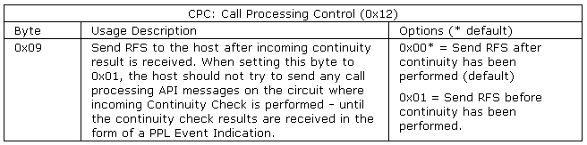
The CSP makes this decision based on the configuration byte 0x09 in the CPC component (0x12). Setting this configuration byte to 0x01 allows the CSP to send the RFS to the host upon receiving an IAM with continuity request. The host can then propagate this IAM with NoC set to continuity check on a previous circuit. If the configuration byte is set to 0x00, the RFS is sent to the host only after a COT- success is received.
Both these cases are shown in the call flows in corresponding example.
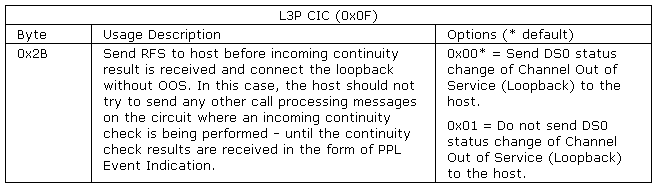
When changing the configuration byte 0x09 in component 0x12 to 0x01, configuration byte 0x2b in component 0x0f must also be set to 0x01.
The host should not try to send any call processing API on the circuit where incoming Continuity Check is being performed, until continuity check results (of pass) are received in the form of a PPL Event Indication.
Exchange B will propagate the COT coming from Exchange A only if it is COT –passed.
In case, Exchange B receives COT-fail from Exchange A, it is not propagated to Exchange C and Exchange C clears the call upon the expiration of timer T8.
Example - Continuity Check on Previous Circuit
In the call flow below, Exchange B waits for COT results before propagating the IAM.
On component 0x12, configuration byte 0x09 is set to 0x00, send RFS after continuity is performed.
On component 0x0F, configuration byte 0x2B is set to 0x00, send DS0 status change of Channel Out of Service (Loopback) to the host.
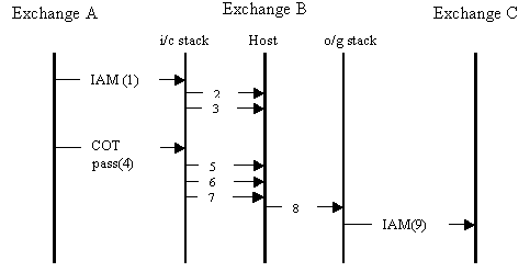
Call Outs
1. The IAM with continuity check is required on this circuit.
2. The PPL Event Indication of 0x01 from component 0x12 (IAM received with the Continuity Check indicator set.)
3. The DS0 status change of OOS (maintenance loopback) is sent only if configuration byte 0x2B of component 0x0F is set to 0x00.
4. The ISUO message of COT success is sent.
5. The PPL Event Indication 0x02 from component 0x12 (COT success from CPC).
6. DS0 status change of in-service.
7. RFS (Request For Service) from L4 to host.
8. Outseize Control message from host to L4.
9. IAM (continuity check not required).
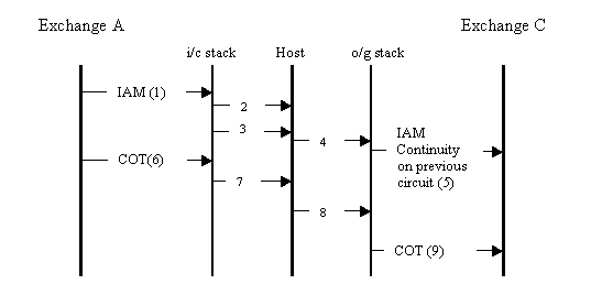
Call Outs
1. IAM (continuity check on this circuit)
2. PPL Event Indication of 0x01 from component 0x12 (IAM received with Continuity Check indicator set.)
3. RFS (Request for Service) from L4 to host. This is sent without waiting for a COT success message as configuration byte 0x09 is set to 0x01
4. Outseize Control message.
5. IAM (continuity check on previous circuit).
6. COT success.
7. PPL Event Indication of 0x02 from component 0x12 (COT success).
8. PPL Event Request 0x0D from component 0x0F (COT success).
9. COT success propagated.
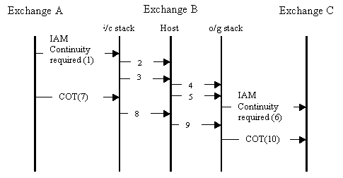
In the following call flow, Exchange B propagates IAM with continuity test on previous circuit. COT failure is not propagated to the destination exchange.
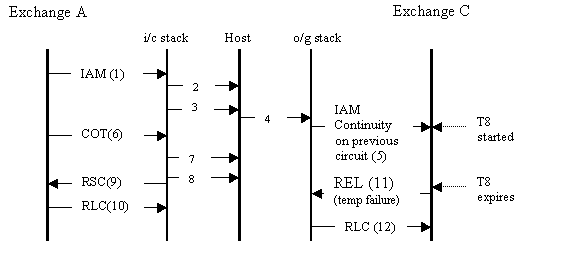
Call Outs
1. IAM (continuity check on this circuit).
2. PPL Event Indication of 0x01 from component 0x12 (IAM received with Continuity Check indicator set).
3. RFS (Request for Service) from L4 to host. This message is sent without waiting for a COT success message as configuration byte 0x09 is set to 0x01.
4. Outseize Control message.
5. IAM (continuity check on previous circuit).
6. COT failure.
7. PPL Event Indication of COT fail.
8. Channel release (0x0049).
9. RSC (Reset Circuit).
10. RLC (Release Complete).
11. REL (temp failure) on T8 expiration on Exchange C.
12. RLC (Release Complete).
Components involved:
• CPC (0x12)
• L3P CIC (0x0F)
Timers Involved
• CPC
• T8: Wait for COT message
Configuration Bytes Involved
Incoming and Outgoing Continuity
In some cases, both the incoming and outgoing legs of a call have continuity required on the circuit as shown in the call flow in the example. See Example - Incoming and Outgoing Continuity.
In such cases Exchange B can determine if it wants to wait for a COT success message from Exchange A before sending a COT success message to Exchange C.
In case Exchange B wants to wait for incoming COT report before sending an outgoing COT success, Exchange C will get a combined COT success for the continuity check required for this circuit and the previous circuit.
1. Exchange C receives a COT success message: Means that the continuity of this circuit (between B and C) AND all the preceding circuits for which the continuity test was in progress (like between A and B) has been verified.
2. Exchange C receives a COT failure message: Means that continuity on this circuit (between B and C) has failed
3. Exchange C does not receive a COT message: Means that a previous circuit (like between A and B) might have failed the continuity test. Exchange C does not need to know which circuit failed as long as it is not its own (in which case it is required to start a continuity recheck loop back)
If the Exchange B chooses not to wait for the continuity success message, Exchange B will send a COT success or failed message as soon as the continuity test between B and C is done and the call will proceed beyond Exchange C (in case the COT was successful). There can be two cases here:
1. If Continuity test passes between Exchanges B and C but fails between Exchanges A and B, then Exchange B incoming side will release the call and sends a PPL Event Indication of COT failure to the host. On the outgoing side (between B and C), the onus lies with the host to release the call and free the outgoing circuit.
2. If Continuity test passes between Exchanges B and C and between Exchanges A and B, Exchange B should not propagate the COT message received to the outgoing side and should let the call complete.
Example - Incoming and Outgoing Continuity
The host sends a PPL event request of 0x0C to component L3P CIC component (0x0F) to make the CSP (Exchange B) wait for the incoming COT report (from Exchange A) before sending COT success to Exchange C.
At Exchange B the host passes information of the incoming COT report to the outgoing L3P (and hence CPC) component by sending a PPL event request of 0x0d to the L3P component. This request conveys an incoming COT success.
Exchange B propagates COT success only when both inbound and outbound continuity tests pass.
1. IAM (continuity check on this circuit)
2. PPL event indication of 0x01 from component 0x12 (IAM received with Continuity Check indicator set)
3. RFS (Request For Service) from the CSP to the host. This is sent without waiting for a COT success message as config byte 0x09 is set to 0x01
4. Outseize Control message
5. PPL Event Request 0x0c from component 0x0f to indicate CPC to wait for incoming COT report when continuity check is being performed on previous circuit AND this circuit (i.e. both incoming and outgoing continuity are being performed).
6. IAM (continuity check on this circuit)
7. COT success
8. PPL event indication of 0x02 from component 0x12 (COT success)
9. PPL event request 0x0d from component 0x0f (COT success).
10. COT success propagated. This is sent only after a successful continuity test is done on circuits between Exchanges B & C and between A & B.
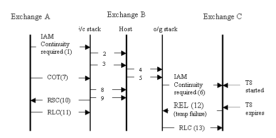
Exchange B does not propagate COT when the inbound COT fails.
1. IAM (continuity check on this circuit)
2. PPL event indication of 0x01 from component 0x12 (IAM received with Continuity Check indicator set)
3. RFS (Request For Service) from L4 to host. This is sent without waiting for a COT success message as config byte 0x09 is set to 0x01
4. Outseize Control message
5. PPL event Request 0x0c from component 0x0f to indicate CPC to wait for incoming COT report when continuity check is being performed on previous circuit AND this circuit (i.e. both incoming and outgoing continuity are being performed).
6. IAM (continuity check on this circuit)
7. COT Failure
8. PPL event indication of 0x03 from component 0x12 (COT failure)
9. Channel released (0x0049)
10. RSC (Reset Circuit)
11. RLC (Release Complete)
12. REL (temp failure) on T8 expiration on Exchange C
13. RLC (Release Complete)
Components Involved
• CPC (0x0012)
• L3P CIC (0x000F)
Timers Involved
• CPC
• T8 Wait for COT message
PPL Information for Continuity
The following summarizes the PPL information used for ANSI ISUP Continuity. Refer to SS7 PPL Information for the details of each component listed below.
Event Requests
• L3PCIC (0x000F), 0x0C, 0x0D
Event Indications
• Call Processing Control (0x12), 0x01-0x08
• Continuity Recheck Outgoing (0x83), 0x01-0x05
Configuration Bytes
• Call Processing Control (0x12), 0x09
• L3PCIC (0x000F), 0x2B
• Continuity Recheck Outgoing (0x83), 0x0A, 0x0B
PPL Timers
• Call Processing Control (0x12), 0x01
• Continuity Check Outgoing (0x14), 0x18
• Continuity Recheck Incoming (0x15), 0x01-0x03
• Continuity Recheck Outgoing (0x83), 0x01, 0x19, 0x0A
Host Controlled Continuity
The continuity feature as implemented on the CSP may prove ineffective when the host wants to specifically take control of the continuity procedure. A typical example where this may be required is in situations where the Voice circuits and Signaling links do not reside on the same CSP or where the voice circuits being used for the call are virtual circuits. This section mentions the changes made in the ISUP layer to implement Host controlled Continuity Check procedure.
Host controlled continuity has been implemented in a way that it does not impact the existing COT procedure. A configuration byte 0xCC has been introduced in the CPC components of ISUP, which when left to its default value of 00 will leave the existing continuity procedure as it is. When this configuration byte is changed to 01, the following changes in functionality take place:
• All COT processing in CPC is bypassed.
• All COT related inter-component messaging is bypassed.
• The COT, CCR and LPA (ANSI) messages received by SPRC are directly propagated to the Host via the CPC. This introduces new PPL event indications to the Host.
• The host will now be able to send PPL event requests for COT, CCR and LPA.
The onus of performing the continuity test and sending the COT (success/failure) to the CSP is on the host application. CSP has no control and no involvement in the continuity test procedure.