You are here: CSP Developer’s Guide: Overview > 10 Configuring Multi-Node Systems > Expanding the EXNET Ring

This section describes the passive addition of an CSP node to an active, non-redundant EXNET ring. This feature allows for easy ring expansion without disruption of voice traffic in an operating system. This feature describes the normal ring mode. However, if you want to use this procedure to use the enhanced fault tolerance ring mode feature, omit steps 6 and 10 from the following procedure. (The Enhanced Fault Tolerance Ring Mode is described in the following section.)
Follow the steps below:
1. Power Up New CSP Node.
The new CSP node must be powered up, before any connections (Ethernet, fiber optic) are made. The CSP Power-On Diagnostics will routinely verify the performance of the CSP with installed cards.
2. Establish Ethernet Connection to host.
In order to configure the new CSP node, the node’s Ethernet interface must be connected to the common Ethernet network before being connected to the host.
Important! Before making an Ethernet connection to the new CSP node which is about to be added to the active EXNET ring, make sure that the new CSP node has default configuration settings (for example, Power-On Reset).
3. Download System Software.
The new CSP node must run the same CSP software version as the CSP nodes in the active network. If not, download the correct CSP software version from the host to the new CSP node. After downloading is complete, the new CSP node automatically restarts execution of the new system software, and is ready for further configuration.
4. Assign Logical Node ID.
Assign the new CSP node a new Logical Node ID. This is done by the host sending an Assign Logical Node ID (0x10) message, to the new CSP node. The Logical Node ID allows the new CSP node to use API messages in further configuration steps.
5. Perform RIC Runtime Diagnostics.
To ensure proper functionality of the new CSP node with the EXNET Ring Interface Card (RIC), perform the RIC Runtime Diagnostic procedure. This procedure is based on the new CSP node receiving the Ring Configure (0x74) message with the RIC Diagnostics (0x04) entity.
|
API Message Name |
API Message Code |
Entity Name |
Entity Code |
Diagnostic Type |
|---|---|---|---|---|
|
Ring Configure |
0x74 |
RIC Diagnostics |
0x04 |
[0x01.0x04] |
The Diagnostic Type in the table above specifies one of four different types of the RIC diagnostic procedure:
• Normal mode, Internal loop back (where the I/O hardware is instructed to internally loop back the I/O port)
• Normal mode, External loop back (where the fiber opticfiber optic cable is required to loop back externally both I/O ports)
• Forced mode, Internal loop back (where the I/O hardware is instructed to internally loop back the I/O port)
• Forced mode, External loop back (where the fiber optic cable is required to loop back externally both I/O ports)
Important! The Diagnostic Type [normal mode] does not allow execution of RIC Diagnostic Procedure while the EXNET ring is up and running. Performing the RIC Diagnostic will bring the EXNET ring down.
The Diagnostic Type [external loop back mode] can be used when both I/O ports of CSP node are externally looped back with fiber optic cable.
6. Prepare New CSP Node for Addition to EXNET Ring (Not used or ignored in Enhanced Fault Tolerance).
To configure the new CSP node for non-disruptive addition into the active EXNET ring, the host notifies the new CSP node by sending the Ring Configure (0x74) message with the Prepare For Addition (0x05) entity.
|
API Message Name |
API Message Code |
Entity Name |
Entity Code |
|---|---|---|---|
|
Ring Configure |
0x74 |
Prepare for Addition |
0x05 |
7. Set-up EXNET Ring Configuration Parameters for the New CSP Node.
In order to prepare the CSP node and the EXNET Ring Interface Card for active participation in data exchange over the EXNET ring, the following configuration elements must be defined:
• Logical Ring ID must be assigned. It must be the same ID as the ring to be expanded.
• The RIC I/O port Transmit mode must be set according to user requirements for the Transmit-Receive or Receive-Only mode.
• The new CSP node's Number Of Packets must be defined (if the Transmit-Receive mode is chosen for the RIC). If the Transmit-Receive mode is set, there must be enough available bandwidth on the EXNET Ring to accommodate the new CSP node.
All parameters specified above are configurable by sending the Ring Configure message with selective entities to the new CSP node as follows:
|
API Message Name |
API Message Code |
Entity Name |
Entity Code |
|---|---|---|---|
|
Ring Configure |
0x74
|
Logical Ring ID |
0x01 |
|
Transmit Mode |
0x02 |
||
|
Number of Packets |
0x03 |
||
|
Ring Mode |
0x0A |
8. Send Loop Back Port message.
Before sending the Loop Back Port message make sure that there are no other ports in existing CSP node configuration already in the looped back mode. (Sending the Loop Back Port message in this case, could cause some nodes to become isolated.)
Send the Loop Back Port message before making any change in physical connection scheme regarding the new CSP node.
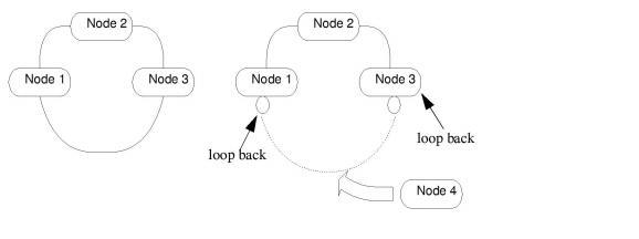
Disconnect the existing fiber optic ring between two adjacent nodes (selected by a user), to allow the new CSP node to join the EXNET ring. The two adjacent nodes in existing configuration must loop back to their respective I/O ports. For example Node 1 and Node 3 in Loop Back of Adjacent CSP Nodes so that the transmission path over the EXNET ring still exists, keeping the ring up and running.
In order to force respective I/O ports (of two adjacent nodes) working in loop back mode, the Ring Configure (0x74) message with Loop Back Port (0x07) entity must be sent to one of adjacent nodes.
|
API Message Name |
API Message Code |
Entity Name |
Entity Code |
|---|---|---|---|
|
Ring Configure |
0x74 |
Loop Back Port |
0x07 |
Important! The Loop Back Port (0x07) message must be sent to only one CSP node, which is expected to change its "A" I/O port, to work in loop back mode. The adjacent CSP node will be automatically notified about this message being processed, and its "B" I/O port will become looped back. The ID of this CSP node is included into the Loop Back Port message as a parameter.
Figure 10-12 Loop Back of Adjacent CSP Nodes
9. Connect fiber optic Cable to New CSP Mode.
Once the fiber optic cable between Node 1 and Node 3 does not carry ring traffic because the respective ports of these two nodes work in looped back mode, the existing fiber optic connections can be expanded to incorporate the new Node 4 into the ring.
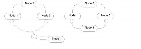
The Node 4 I/O ports are both connected with fiber optic cables to Node 1 and Node 3 as shown in fiber optic Connections to Add New CSP Node. This connection does not provide any voice traffic exchange to and from Node 4, because the respective I/O ports of Node 1 and Node 3 still remain looped back.
Figure 10-13 fiber optic Connections to Add New CSP Node
10. Send Expand Ring message (Not used or ignored in ERFT. In ERFT the node signals to its adjacent nodes to initiate port expansion.)
At this point, the existing EXNET ring is about to be expanded with the new CSP Node 4. To allow Node 4 to become active in the EXNET ring, both Node 1 and Node 3 must remove the loop back from their respective I/O ports. To avoid the possibility of ring going down, removal of the loop backs on both Node 1 and Node 3 must be done essentially at the same time.
For the purpose of expansion of the EXNET ring with the new CSP Node 4, the Ring Configure (0x74) message with Expand Ring (0x06) entity must be sent down to either Node 1 or Node 3, which has one looped back I/O port.
|
API Message Name |
API Message Code |
Entity Name |
Entity Code |
|---|---|---|---|
|
Ring Configure |
0x74 |
Expand Ring |
0x06 |
When both CSP nodes, Node 1 and Node 3, are not looped back, the EXNET ring data is routed through Node 4. At this point, Node 4 is internally configured not to transmit its own packets onto the EXNET ring.
11. Send the Add Node Message.
At this point there are no looped back I/O ports in the EXNET ring, and the ring data is routed through Node 4 (both I/O ports remain open). For Node 4 to actively participate in the EXNET ring, the Ring Configure (0x74) message with Add Node (0x08) entity must be sent to Node 4.
|
API Message Name |
API Message Code |
Entity Name |
Entity Code |
|---|---|---|---|
|
Ring Configure |
0x74 |
Add Node |
0x08 |
Upon receiving this message, Node 4 attempts to verify if the Master Node of the EXNET ring acknowledges its presence on the EXNET ring. When this is verified successfully, Node 4 turns on its transmitter (if configured for Transmit/Receive mode) to allow its own packets to appear on the EXNET ring.
12. Perform Final Verification.
The final verification must be performed on all CSP nodes directly involved in the passive addition of the new CSP node to active ring (Node 1, Node 3 and Node 4):
• The EXNET ring should be in service.
• Respective I/O port on Node 1, which prior to the reconfiguration was looped back, should be open.
• Respective I/O port on Node 3, which prior to the reconfiguration was looped back, should be open.
• Both I/O ports of the Node 4 should be open.
13. User configuration on the new CSP node.
At this point, you can configure required CSP options on the new CSP node. For this purpose, the API messages can be used.