You are here: SwitchKit CSA User’s Guide > 3 Configuring Line Cards, Spans, and Channels > Configuring Virtual Cards

This procedure describes how to configure virtual cards for T1, E1, and VoIP protocols. The J1 protocol is configured on the Virtual E-ONE card.
For more information on the T1, E1, or J1 protocols, see the Developer’s Guide: Line Cards.
Before you begin
You must have a node view window open in configuration mode. Before you configure a VOIP protocol, you must locate your SIP and virtual span license files (typically named, license.cfg) which contains license keys. To configure virtual T-ONE, E-ONE or J-ONE cards, you must have an SS7 user part license. Contact your sales representative for these licenses. To install a license key, you must use the General Node Configuration dialog box. See General Node Configuration for the procedure on opening the license key.
Since virtual slots in the switch are each assigned a card type as if they were installed as physical cards, both matrix controller diagnostics and alarms function normally.
If a virtual card is added, removed or reconfigured in a slot with another card already in place, that card and the specified configuration will be lost.
Configuring Virtual Cards
The following steps explain the virtual card configuration.
1 To add a virtual card, do one of the following:
• In the node view, right-click the blue area around the card slots or in an unused slot and select Add Card.
• Go to the Configuration menu and select Node Configuration ®Add Card.
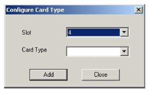
The Configure Card Type dialog box opens.
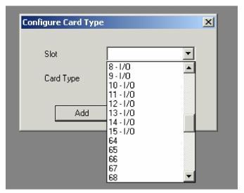
2 For the Slot, select a physical slot that is unused. Or, you may select from the drop-down list a virtual slot which starts at number 64. See the next screen shot.
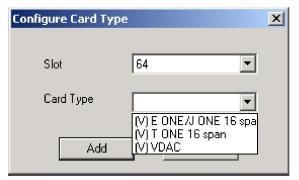
3 For the Card Type, select (V) VDAC, (V) E ONE /J ONE 16 Span, or (V) T ONE 16 Span from the drop down list.
Note: A virtual VDAC card, (V) VDAC, has all the functionality of both the VDAC-ONE and IP Network Interface Series 2 cards.
4 Click Add. Repeat steps 2-4 for each virtual card you want to add.
5 Click Close.
6 If you have configured a physical slot, skip this step and continue with the next.
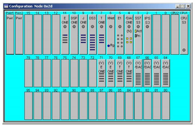
If you have added a card to a virtual slot, in the node view you must right-click the blue area around the card slots or in an unused slot to select Show Virtual View from the drop-down list.
The next screen shot shows the virtual view:
Important! If you do not want internal routing tables to be created for the Virtual VDAC card, you must use the Configure PPL Tool dialog box to uncheck this option. See Specifying PPL Files
7 Right-click the label of the virtual card that you are configuring and select Span Configuration from the drop-down list. A dialog box similar to the one in the next screen will open:
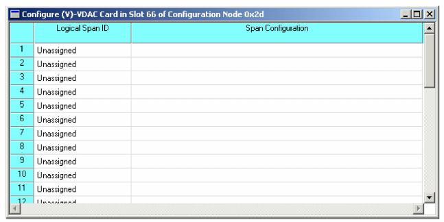
8 Highlight a single span or a group of spans and right-click the highlighted area. Select Assign Logical span ID from the drop-down list. The Configure Starting Span ID dialog box opens.
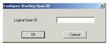
9 Enter a number for a single span or a number which represents the beginning of a contiguous group of logical span IDs.
Important! For a 10,000 channel license, the CSA allows you to configure 10 virtual VDAC cards for a total of 315 virtual spans. Nine of those cards support 32 spans each but the tenth will only support 27 spans. With virtual T-ONE cards, the CSA allows you to configure 27 virtual T-ONE cards for a total of 420 virtual spans. Twenty-six of those cards support 16 spans but the 27th virtual card only supports 4 spans. With virtual E-ONE or J-ONE cards, the CSA allows you to configure 20 virtual E-ONE or J-ONE cards for a total of 315 virtual spans. Nineteen of those cards support 16 spans but the 20th virtual card only supports 11 spans. If you configure too many spans or cards, the switch will not accept the configuration.
10 Click OK.
11 To complete your configuration of the virtual T-ONE card see Configuring the T-ONE Card. To complete your configuration of the virtual E-ONE card see Configuring the E-ONE Card. To complete your configuration of the virtual VDAC card see Configuring VDAC-ONE, starting at Step 9 with the Channel Group Configuration dialog box.

Note
Configuration changes are not sent to the CSP until you select the menu: Configuration®Configure Through SwitchMgr ®Send Only Modified Configuration To Switch.