You are here: SwitchKit CSA User’s Guide > 5 Configuring VoIP Cards and Features > Configuring VDAC-ONE

This procedure describes online configuration of the VDAC-ONE (Voice-Data Access Concentrator) card.
Before you begin
For offline configuration, you must have a node view window open in configuration mode. If you want to configure online, make sure that the LLC and SwitchManager are running. For information on running LLC and SwitchManager refer to the SwitchKit documentation. For offline or online configuration, you must enable advanced IP routing in either the SIP configuration or the H.323 IP Signaling Series 3 card resource attributes configuration. See step Under Advanced IP Routing, if you want to enable this option, select it., Configuring SIP or step Select Enable Advanced IP Routing, if you want this feature enabled., Configuring H.323 .
The VDAC-ONE card
The VDAC-ONE card performs two-way conversion between circuit-switched data and packet-switched Ethernet data. The IP Signaling Series 3 card enables the CSP to communicate with H.323 entities in the network architecture. For information beyond the default values provided, please refer to the Converged Services Platform, Developer’s Guide: Internet Protocol.
Configuring VDAC-ONE
The following steps explain the VDAC-ONE configuration.
1 From the node view, invoke the VDAC-ONE configuration dialog box by doing one of the following:
• Double-click the VDAC-ONE card in the node view.
• Select the VDAC-ONE card in the node view. Go to the Configuration menu and select Card®VDAC Configuration.
• Right-click on the VDAC-ONE card in the node view and select VDAC Configuration from the menu.
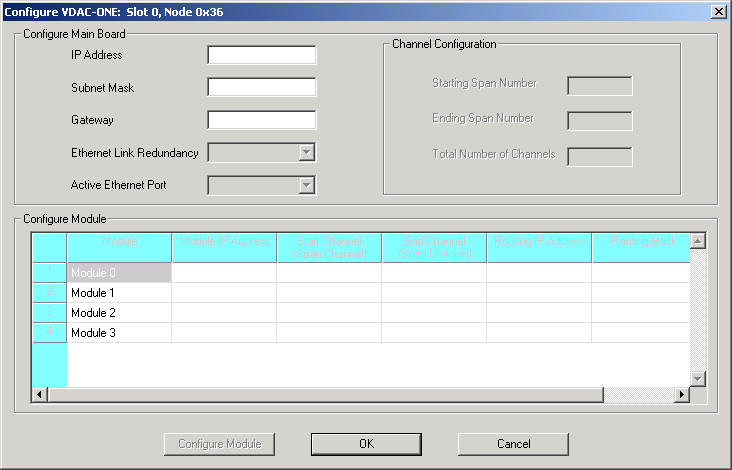
The Configure VDAC-ONE... dialog box opens. See the next screen shot.
2 Enter the IP Address and Subnet Mask of the main board. After these values are entered and you tab to the Gateway field, most of the other fields and module configuration become enabled.
Important! If you do not want internal routing tables to be created for this card, you must use the Configure PPL Tool dialog box to uncheck this option. See Specifying PPL Files. The internal routing tables that are enabled by default create your IP-to-span-channel mapping that is installed on the CSP. Also, a separate config file is added to the SwitchManager file which is also shown in the Configure PPL Tool dialog box in Specifying PPL Files.
3 Specify the settings for Ethernet Link Redundancy and Active Ethernet Port.
4 To assign all logical span IDs for the VDAC-ONE card, specify the Starting Span Number.
Important! The CSA provides default routing by mapping the specified spans with the IP Addresses of the VDAC-ONE modules.
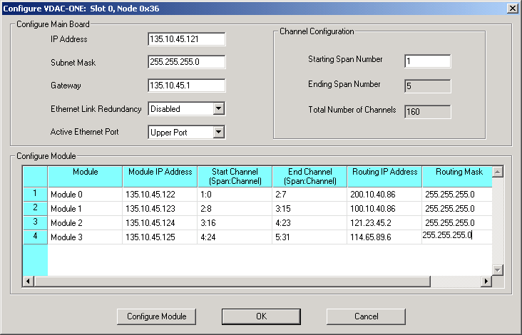
5 Specify the IP addresses for each Module in the Configure Module group. When you click out of the module IP address cell, the Start Span:Channel and End Span:Channel get populated automatically from having specified the Starting Span Number in the Channel Configuration group box.
6 If you are using IP-based routing, enter the Routing IP Address and Routing Mask of the endpoint that is within or outside the main board network.
These fields are enabled if you have done either of the following:
• Selected Enable Advanced IP Routing in the SIP configuration dialog box.
• Selected Advanced IP Routing in the H.323 IP Signaling Series 3 card resource attributes configuration dialog box.
See the next screen shot with example data.
7 Select the module you want to configure and click Configure Module. The Configure Resource Attributes VDAC-ONE:... dialog box opens for the selected module.
The dialog box opens with default values. You can change the values, if required. The valid range of values for the fields, 2833 Dynamic Payload Type and 2198 Dynamic Payload Type, is 0-127 except for 102, 103, and 105.
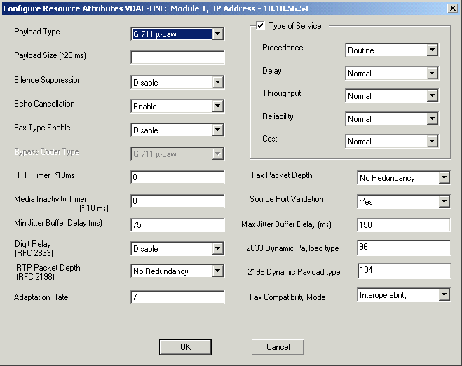
8 Click OK to close the Resource Attributes VDAC ONE... dialog box.
9 Click OK to close the VDAC-ONE configuration dialog box.
10 You may now configure the Channel Group and Range for the VDAC-ONE card.
11 To invoke the Channel Group Configuration dialog box, do one of the following:
• Right-click the blue area around the card slots and select Channel Group Configuration from the menu.
• Go to the Configuration menu and select Node Configuration®Channel Group Configuration.
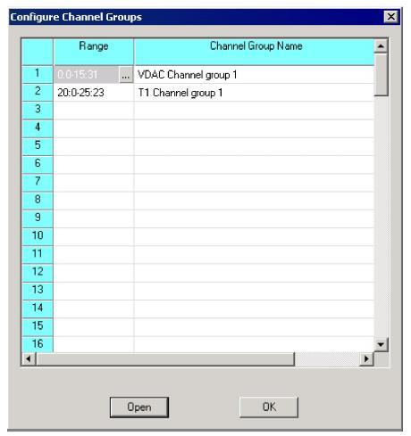
The Channel Group Configuration dialog box opens. If you are configuring the Channel Group for your VDAC-ONE card for the first time, the table cells are empty. See the next screen shot.
The VDAC-ONE configuration shown in the next screen shot includes example values.
12 Double-click the table cell in the Range column, the Specify Span Range dialog box opens as shown below:
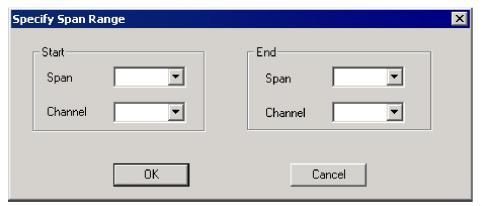
13 Specify the range with the drop-down list for the Start Span and Channel, and End Span and Channel. Make a selection based on the range of spans generated in To assign all logical span IDs for the VDAC-ONE card, specify the Starting Span Number..
14 Click OK to close the Specify Span Range dialog box.
15 In the Channel Group Configuration dialog box, click Open to invoke the Configure VDAC Channels dialog box. The dialog box opens with default values. Note that the Interworking group box refers to routing.
Excel recommends configuring Answer Supervision Mode with Propagate Answer and Notify Host selected as shown in the next example screen shot:
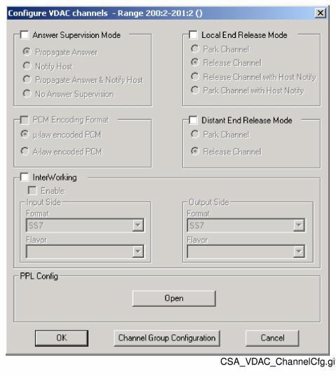
16 Specify your settings by marking check boxes and selecting from the drop-down lists.
17 Click OK to close the Configure Channel Range Messages dialog box.
18 In the Configure Channel Groups dialog box, fill in a name for your channel group.
19 Click OK to close the Configure Channel Groups dialog box.

Note
Configuration changes are not sent to the CSP until you select the menu: Configuration® Configure Through SwitchMgr® Send Only Modified Configuration To Switch.