
The following requirements have to be met for the installation of the Dialogic® Diva® System Release software:
Notes for Dialogic® BlueTM Telephony Boards:
This chapter lists the supported boards and switch types and it gives an overview of the Dialogic® Diva® softIP for SIP software and its features.
The Dialogic® Diva® System Release Software supports the following and Dialogic® Diva® Media Boards and Dialogic® BlueTM Telephony Boards
A maximum of eight Diva Analog, BRI, 4BRI, PRI, V-2PRI, four Diva V-4PRI, or two Diva V-8PRI Media Boards are supported in one computer. Diva Media Boards with DSPs can also function as resource board for the Diva softIP software. See Using Dialogic® Diva® Media Boards as DSP Resource Board with the Dialogic® Diva® softIP Software for more information. For more information about the Diva softIP software module, see Dialogic® Diva® softIP for SIP Software.
Dialogic® Diva® BRI Media Boards
|
|
|
|
|
|
|
|
|
|
|
|
Dialogic® Diva® PRI Media Boards
Diva PRI: |
Diva UM-PRI |
Diva V-PRI: |
|
|
|
|
|
|
|
|
|
|
|
|
|
|
|
|
|
|
|
|
|
Dialogic® Diva® multiport V-PRI Media Boards
|
|
|
|
|
|
|
|
|
|
Note: "HS" stands for the half size and "FS" for the full size board format.
Dialogic® Diva® Analog Media Boards
|
|
|
|
|
|
|
|
|
|
|
|
Dialogic® Diva® softIP for SIP software (virtual media board for IP)
Dialogic® BlueTM Telephony Boards
The Dialogic® Diva® System Release Software supports the following Dialogic® BlueTM Telephony Boards (A maximum of two Telephony Boards are supported in one computer. See also System requirements):
Note: "S" stands for Software and "LP" stands for "Low Profile" board format.
With the licensed-based Dialogic® Diva® softIP for SIP software module, the Diva System Release software offers a middleware that enables existing voice Media Board in that it provides functions such as voice and fax transmission, DTMF tones and supplementary services as well as conferencing between ISDN and fax applications to be fully integrated into Voice over IP networks using any standard Ethernet adapter. Technically speaking, the Diva softIP software is comparable to a Diva Media Board in that it provides functions such as voice and fax transmission, DTMF tones and supplementary services as well as conferencing between ISDN and VoIP connections, as shown in the graphic.
If the Diva softIP software and a Diva Media Board are combined in one system, they can concurrently be connected to TDM and IP systems and they can serve as basis for PSTN-IP gateway applications. See also Using Dialogic® Diva® Media Boards as DSP Resource Board with the Dialogic® Diva® softIP Software.
To use the Diva softIP software, you need to purchase the required number of licenses with your Dialogic® Diva® Media Board vendor and activate them in the Dialogic® Diva® Configuration Manager. See License activation for more information. There are two types of licences: Telephony (for voice applications) and Telephony+Fax (for voice and T.38 fax applications).
Note: Line Interconnect is not available for the Diva softIP software grouped in an M-Board.
Explicit Call Transfer with consultation call with primary call not on hold.
For more information about Proxy and Registrar configuration, see the Dialogic® Diva® softIP Online Help file.
Note: The availability of the line speed depends also on the gateway or the remote IP Fax terminal.
* Based on T.38 without own Soft Fax stack, feature depends on VoIP Gateway/Terminal.
Dialogic® Diva® softIP for SIP software (virtual media board for IP)
All Diva Media Boards with DSPs, except Dialogic® Diva® PRI/E1/T1-8 PCI Media Boards, can be used as conventional TDM boards and/or as DSP resource board. In the resource board mode, the external interfaces are disabled and the Diva Media Board functions only in combination with the Diva softIP software and thus provides functions to voice, clear channel fax and clear channel modem connections. Clear channel fax can be used by PSTN-IP gateways that do not support T.38 fax so that the fax signal is transmitted in clear channel mode.
If the Diva softIP software is used together with the Diva Media Board as resource board, clear channel fax is used for fax transmission. If the Diva softIP software is used as stand-alone product, T.38 Fax is used.
If Diva Media Boards with DSPs and the Diva softIP software are installed in the same system, calls that are initiated without the need to allocate hardware DSP resources (e.g. voice) are preferably routed via the Diva softIP software. If all available channels of the Diva softIP software are used and no channels of the Diva Media Board are reserved for DSP usage, the remaining DSP-enabled channels of the Diva Media Board are also used for non DSP-related calls.
During a call, the call characteristic may change and may require a switchover from the Diva softIP board to the Diva Media Board or vice versa. In this case, the Combined Board internally reroutes the call using the required resources. To enable the switchover, you need to combine both boards in the Board Configuration page.

Dialogic® Diva® Media Boards currently support the following switch types:
Note: The Generic QSIG switch type can be used for the majority of PBXs
Note: Many European PBXs use the regular ETSI protocol (PRI and BRI).
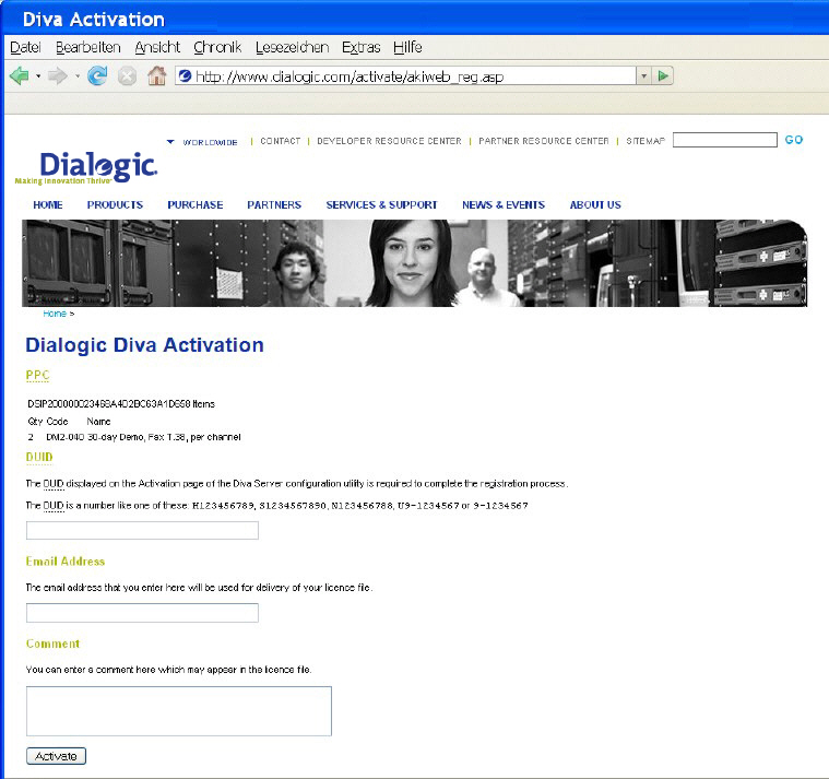
After you have installed your Dialogic® Diva® product, you might need to generate a license file and activate it in the web interface to unlock the required functionality in the product. To do so, you need the Proof of Purchase Code (PPC) delivered with your product and the Device Unique ID (DUID) of the installed product. See below for more information about the PPC and DUID.
For the Dialogic® Diva® System Release LIN software, licenses are available as free 30-day test licenses. For the Dialogic® Diva® softIP for SIP software a free test license for two channels (voice and fax) is available on the Dialogic web site www.dialogic.com. If you use the Diva softIP software in a virtualized environment, see also Licensing the Dialogic® Diva® softIP Software in virtualized environments.
Note: You can purchase the license with your Dialogic® Diva® Media Board vendor.
You need to generate a license file if you have installed one of the following products and purchased a license for one of the following functionalities:
Product |
Functionality |
|||||||||||||||||||||||
Dialogic® Diva® System |
|
|||||||||||||||||||||||
Dialogic® Diva® V-1PRI, V-2PRI, V-4PRI, or V-8PRI Media Board
|
The Diva V-1PRI PCIe HS, Diva V-2PRI PCI, Diva V-2PRI PCIe HS, and Diva V-4PRI PCIe FS Media Boards offer full TDM channel density via licenses with full performance for all modem and fax features. With the Diva V-4PRI PCI, Diva V-4PRI PCIe HS (12 DSPs) and the Diva V-8PRI PCIe FS (24 DSPs) Media Boards, V.90, data modem support, and V. 34 fax support are available via licenses but not on all channels, due to limited DSP V.90 resources. V.32 data moden and V.17 fax can be done on all channels. The following modem and fax features are supported via licenses:
|
Device Unique ID (DUID)
The DUID binds the installed Dialogic® Diva® product to your PC (PC fingerprint).
To get the DUID:
See To register your PPC and DUID for information about generating a license.
Proof of Purchase Code (PPC)
When you purchase the license, you will receive a PPC either in printed form or via email. By registering this PPC, you represent and warrant that you lawfully purchased the license.

The date set in the system settings of your computer must be correct. Otherwise, you cannot add your license file.
Now, the functionality is unlocked for the feature set you acquired with your license.
In virtualized environments the Diva softIP software license is bound to your system with the PC fingerprint only. The WIBU-Key USB dongle cannot be used for licensing purposes, because an access to the USB is not supported by virtualized environments. The license is bound to several hardware components of the PC, including the MAC address. Each virtual machine (VM) has its own MAC address; therefore, a separate license is required for each active VM with the Diva softIP software installed. Separate licenses are also needed for environments with parallel services, e.g., VM 1 operates a fax server using the Diva softIP software and VM 2 operates an IVR system using the Diva softIP software. Also, since the Diva softIP software license is bound to the hardware components as well, the Diva softIP software license will become invalid if you move the VM to another hardware platform.
You should assign a fixed MAC address to avoid that it changes, e.g., after copying the virturalized environment to a different place, or after restarting or reconfiguring the PC, otherwise the Diva softIP software license will become invalid.
If two VMs are used for failover only and are not active at the same time, the same MAC address may be assigned to both VMs, the active VM and the passive failover VM. In this case, the Diva softIP software license can be installed on both VMs, but you need to make sure that only one of the VMs is active, otherwise it may cause a MAC address conflict and the network communication may be interrupted.
Notes:
The following steps provide an overview of the installation and configuration procedure for the Diva System Release software:
The Dialogic® Diva® System Release software can be installed on a wide range of Linux distributions.
The software consists of an integrated installer, providing automatic detection of the presence and type of the system package manager:
To install the software, follow these steps:
sh <download path>/Diva4Linux_installer_<nnn>.bin<download path> is the path where you stored the downloaded installer package, and <nnn> is the software version and build number.-t <path>, you can specify the temporary working directory for the installer. The default is /tmp/divas../BuildThe following files are included in the package:
The Config script (located in the /usr/lib/opendiva/divas directory) is a setup wizard that detects the installed Dialogic® Diva® Media Boards and additional applications.
The setup wizard generates the divas_cfg.rc file (located in the /usr/lib/eicon/divas directory) that is used to start the Diva Media Boards, interface drivers, and additional software at system startup or to start the components manually. You can use the script /usr/lib/opendiva/divas/Start to load and /usr/lib/opendiva/divas/Stop to unload the software manually.
The setup wizard creates the necessary device nodes in the /dev directory:
You can either use the Config script or the web-based Dialogic® Diva® Configuration Wizard to configure the settings for your Diva Media Boards. The following description of configuration options is based on the web-based Diva Configuration Wizard. It is structured as follows:
The Dialogic® Diva® System Release software installs and configures the Dialogic® Diva® WEB Configuration Wizard that allows you to access and configure the Diva System Release software via an HTTP browser.
The installation procedure sets up the port 10005 for HTTP access and 10006 for HTTPS access.
If you do not want to use the Dialogic® Diva® WEB Configuration Wizard, you can disable it with the command: cd /usr/lib/opendiva/divas && sh cfg_util.sh 4. To re-activate the Diva WEB Configuration Wizard, use the command cd /usr/lib/opendiva/divas && sh cfg_util.sh 5.
To access the Diva WEB Configuration Wizard you need to edit the /usr/lib/opendiva/divas/httpd/login/login file and configure your password.
Note that the "login" file must meet the following requirements, otherwise the password will be ignored:
The system and Diva Media Board configuration is divided in two parts:
Online help is available for any system configuration option. To open the online help for a specific parameter, click the parameter and a window with the help text pops up.
At the end of the system configuration, the Dialogic® Diva® WEB Configuration Wizard will prompt you to restart the Diva drivers if necessary. To restart the Diva drivers, go to System control, where you can stop and start the drivers.
Note: Some of the changes, for example, Start driver on system boot or Debug mode for microcode load do not affect the state of the currently running drivers and change only the driver behavior at system or Dialogic® Diva® Media Board start. The Dialogic® Diva® WEB Configuration Wizard ignores changes of these parameters and does not prompt you to restart the Diva Media Board drivers.
Context-specific online help is available for most configuration options. To open the online help for a specific parameter, click the parameter and a window with the help text pops up.
The Board configuration allows you to configure the Dialogic® Diva® Media Boards that are installed in your system as required by your service provider or by the PBX to which the Diva Media Boards are connected.
To start the configuration of a Diva Media Board, select its "board" icon in the Diva Media Board list. The basic configuration parameters are displayed.
Note: This option is not available for all D-channel protocols. A better control of incoming called party numbers is available using the Call Routing Configuration.
Depending on the installed board and the selected D-channel protocol, you might need to configure various advanced parameters. To do so, set View extended configuration to Yes and modify the advanced parameters as required. For further information on advanced parameters, see the online help topic of the respective parameter.
When the board configuration is complete, the Dialogic® Diva® WEB Configuration Wizard stores the parameters list, generates a startup shell script and tries to update the modified parameters via the management interface. If updating via the management interface is not possible, for example, the board is not running or the configuration parameter is not supported by the management interface, the Diva WEB Configuration Wizard prompts you to restart the board.
To restart the board, you can either:
Note: Restarting the Dialogic® Diva® Media Board clears the active connections of this board.
If you select the Hardware status/management icon, you will gain access to the:
The Dialogic® Diva® WEB Configuration Wizard provides access to the following maintenance functions:
The system environment browser allows for viewing information about the:
The Dialogic® Diva® Trace Wizard allows for selecting various trace profiles and thus enables you to trace everything or to suppress unnecessary information in certain scenarios. Detailed information on the various trace profiles is given in the online help. To display the online help for a profile, click its name.
The Diva Trace Wizard also allows you to set the size of the trace ring buffer - a binary file where the trace information is stored - and to start the trace process in the background.
After the trace process is started, you can leave the Diva Trace Wizard or close your HTML browser without affecting the running trace process.
While the trace process is running (and after the trace process is stopped), you can decode, filter, and view the content of the trace ring buffer file with the trace file browser (View trace file).
To stop a running trace process, enter the Diva Trace Wizard again; the Diva Trace Wizard will remember that the trace process is still running, and stop it. After stopping the trace process, you can download the compressed binary trace file.
If you should experience any problems after the installation of the Dialogic® Diva® System Release software, for example, no Dialogic® Diva® Media Boards can be detected, use the Dialogic® Diva® Support Wizard to capture and download in compressed form the information that is required to process your support request. Select one of the following options:
The system log viewer allows you to view the latest kernel messages. You can use this information to control the load and operation of Dialogic® Diva® drivers and to check your system for unexpected errors, driver failures, or exceptions ("Oops").
The trace file browser allows for decoding, filtering, and browsing the trace file without downloading this file to your machine and without stopping the trace process.
The trace file viewer displays a list of the Dialogic® Diva® debug and trace sources information contained in the trace file and it allows you to select the sources of information that you want to view, decode, and display.
The trace viewer highlights messages in the trace information window by the following colors:
To get detailed decoded information on trace and debug messages, click the "highlighted" links in the trace information window.
The call history (call journal/log) is stored as a sequence of files named divalog,divalog.1...divalog.N, where N is the integer number in the /var/log directory. The divalog.N file contains the oldest trace information while the divalog file contains the latest (current) information about the call activities.
You can use the call history viewer to decode the divalog file (call time, duration, type, speed) and view this information without downloading the call history file to your local machine.
To download call history files, click Download. You will receive a text file that displays the various components of the call history information separated by commas. The first line of the file contains the description of the components.
The Dialogic® Diva® Statistics Viewer analyzes the call history files found in the /var/log directory and creates various statistics based on these files. The statistics show the total number of calls related to various periods of time, the ratio of incoming and outgoing calls, the ratio of call types, call duration charts, a peak board load chart, etc.
The statistic information is presented in a graphical format (jpeg) and can be used to analyze the system load and reliability.
If you want to create your own statistics, download the call history files in the call history viewer and apply your own spread-sheet application.
During installation and configuration, the divas_cfg.rc script is automatically generated. This script is used to load protocol, CAPI, and TTY interfaces. On system startup, the Dialogic® Diva® Media Boards will be started by symbolic links named "S03DIVAS4LINUX" and "S06DIVAS4LINUX_NETWORK". These links are created as part of the installation process and are located in the runlevels 2, 3, and 5 of the following directories (system and version dependent): /etc/rc.d/ directories for Red Hat, in the /sbin/init.d/ or /etc/init.d/ directories for SuSE and in the /etc/rcX.d/ directories for Debian and others.
sh /usr/lib/opendiva/divas/cfg_util.sh 2. If you wish to restore these links, execute: sh /usr/lib/opendiva/divas/cfg_util.sh 1. /usr/lib/opendiva/divas/Stop script to stop the Diva Media Board and unload the Dialogic® Diva® drivers. /usr/lib/opendiva/divas/Start script to load the Diva drivers and start the Diva Media Boards. /usr/lib/opendiva/divas/divas_cfg.rc restart <x> command, where <x> is the logical board number./usr/lib/opendiva/divas/divas_cfg.rc restart -1 command.To interpret the Diva Media Board, driver, and trace data the following information is necessary:
Every Dialogic® Diva® Media Board that is installed in the system is a "physical" board. Every physical board contains one or more ISDN or analog interfaces. Each interface is represented in the system by a "logical" board. Example: Three physical Diva Media Boards are installed in the system: a Dialogic® Diva® BRI Media Board, a Dialogic® Diva® PRI Media Board, and a Dialogic® Diva® 4BRI Media Board. The Diva BRI Media Board and the Diva PRI Media Board add one logical board each. The Diva 4BRI Media Boards adds four logical boards to the system. If one physical board contains multiple logical boards, a continuous block of board numbers is allocated to these boards. The first logical Diva Media Board is the "master" board. This board is responsible for the hardware resources of the physical board and for loading, starting, and stopping the logical boards provided by the physical board. In the other aspects (functionality, configuration, selected protocol, debug buffers, and features), the logical boards are independent from the location of their physical boards: on different physical boards or on the same physical board.
After being started, the DIDD (divadidd.[k]o) driver creates the directory /proc/net/isdn/eicon for kernel 2.4.x and the directory /proc/net/eicon for kernel 2.5.x and higher in the proc file system. You can read the file divadidd in this directory (for example by executing cat divadidd) to get version information on the DIDD driver.
After being started, the XDI driver (divas.[k]o) creates the file divas in the /proc/net/[isdn/]eicon directory. You can read this file (for example by executing cat divas) to get version information on the XDI driver. A subdirectory named adapter<no> (<no> is the logical Dialogic® Diva® Media Board number) is created in the directory /proc/net/[isdn/]eicon for every logical Diva Media Board present in the system.
Each adapter<no> directory contains the following files:
info |
You can read this file (cat info) to get information on the Diva Media Board: board name, serial number, number of channels supported by the board, hardware resources assigned to the board, board state. Possible board states are: ready (ready to download and start firmware or fpga), active (operating), trapped (firmware problem, core dump should be generated), unknown (hardware problem), and slave (slave board of a Diva Media Board that supports multiple logical boards) |
group_optimization |
You can read this file (cat group_optimization) to get the current state of this feature (on|off - 1|0). You can write "1" to this file to turn this feature on (echo 1 > group_optimization). You can write "0" to this file to turn this feature off (echo 0 > group_optimization). For further information on this feature, see the online help. |
dynamic_l1_down |
You can read this file (cat dynamic_l1_down) to get the current state of this feature (on|off - 1|0). You can write "1" to this file to turn this feature on (echo 1 > dynamic_l1_down). You can write "0" to this file to turn this feature off (echo 0 > dynamic_l1_down). For further information on this feature, see the online help. |
Global fax configuration options allow for overwriting parameters passed by the fax application to the Dialogic® Diva® Media Board and to control parameters running on the Diva Media Board's T.30 protocols. This provides a high level of flexibility, especially if the fax application does not provide the required parameters.
Fax configuration options
Option |
Description |
Fax speed limit |
Allows to limit the transmission speed. Normally, you do not need to limit the fax speed because the Diva Media Board automatically negotiates the appropriate speed. |
Disable fine resolution |
Disables the transmission of fax messages with high resolution. |
Disable Error Correction Mode (ECM) |
Disables the transmission of fax messages using ECM (Error Correction Mode). |
Use ECM frame length of 64 bytes |
Forces usage of HDLC frames with a maximum length of 64 bytes if transmitting fax messages using ECM (Error Correction Mode). |
Disable 2D fax document compression |
Disables usage of 2D fax document compression. This option also disables the automatic (transparent to application) fax document compression provided by the Diva Media Board in order to increase the effective transfer speed of fax messages. |
Disable T.6 fax document compression |
Disables usage of T.6 fax document compression. This option also disables the automatic (transparent to application) fax document compression provided by the Diva Media Board in order to increase the effective transfer speed of fax messages. |
Disable uncompressed T.6 fax document lines |
In some cases, compression of a fax document line results in a line that is longer than the uncompressed original. The T.6 protocol allows you to reduce the fax transmission time by transmitting such lines without compression. This option disables the line compression optimization. |
Refuse incoming polling requests |
Disables incoming polling requests. |
Hide "total pages" information in fax message |
Hides the "total pages" information field in the fax message. |
Hide "head line" information in fax message |
Hides the "headline" information field in the fax messages. |
Hide "page info" information in fax message |
Hides the "page info" (i.e. message head) field in the fax messages. |
Disable fallback to lower speed on failure |
"Feature fallback" is used to prevent excessive resending of fax documents if working over poor quality lines. The Diva Media Board internally saves the fax ID of the last peer and the results of the fax transmission from this peer. If the results of the last fax transmission were negative and the application starts message re-transmission, the Diva Media Board will detect this and fallback to a lower transfer speed. This setting allows for disabling fallback. |
Dialogic® Diva® Media Boards provide numerous configuration options part of which are only used in special applications. These configuration options are not covered by the Dialogic® Diva® Configuration Wizard.
To get a full list of configuration options, execute /usr/lib/opendiv/divas/divactrl load.
You can apply special configuration options by modifying your Diva Media Board's startup script /usr/lib/opendiva/divas/divas_cfg.rc. In this case, you have to specify special configuration options as well as the standard options in the command line of the /usr/lib/opendiva/divas/divactrl board load utility.
Special configuration options can be changed during run time without restarting the board via the management interface, for example, with the /usr/lib/opendiva/divas/divactrl mantool management interface access utility.
The following procedures will help you to verify if the Dialogic® Diva® Media Board and the service are working properly. After configuring and loading the drivers, it is recommended that you use one or more of the following methods for testing:
This test allows you to test the Dialogic® Diva® Media Board and Dialogic® Diva® TTY interface functionality and link integrity using various bearer protocols supported by your Diva Media Board.
The /usr/lib/opendiva/divas/tty_test utility is located in the /usr/lib/opendiva/divas directory. On the server side, type: /usr/lib/opendiva/divas/tty_test 1 s auto. On the client side, type: /usr/lib/opendiva/divas/tty_test 2 <ISDNnumber> x75. The transfer rate will appear in real time and be updated every time 64 Kbytes of data have been transferred.
Note: Many other options, e.g., bearer protocol, packet size, rate adaptation, are available for the TTY test. Type /usr/lib/opendiva/divas/tty_test for a full list or refer to the section tty_test utility in this document.
This tool allows you to test the Dialogic® Diva® Media Board and CAPI 2.0 interface functionality and link integrity using the X.75/T.70NL bearer protocol. The acopy2 utility is located in the /usr/lib/opendiva/divas directory.
Note: Many other options, e.g., packet size, CPN, SubAddress, and commands are available. Type /usr/lib/opendiva/divas/acopy2 for a full list.
On the server side, type: /usr/lib/opendiva/divas/acopy2 -c<X> -serve /p2048, where 2048 is the packet size for beneficial results and <X> is the CAPI board number that will receive the call.
On the client side, type: /usr/lib/opendiva/divas/acopy2 -c<Y> - n<ISDNnumber>:file2 file1 /p2048, where 2048 is the packet size for beneficial results and <Y> is the CAPI board number that will issue the call.
This tool allows you to test Dialogic® Diva® Media Board and CAPI 2.0 interface functionality and link integrity using the Fax G3 bearer protocol.
The TESTFAX utility is located in the /usr/lib/opendiva/divas directory.
On the server side, type: /usr/lib/opendiva/divas/testfax -serve -c<X>, where <X> is the CAPI board number that will receive the call.
Note: Many other options, e.g., packet size, transmission speed, ECM, SEP/SUB/PWD, compression, fax ID, headline, and commands, are available. Call /usr/lib/opendiva/divas/testfax for a full list.
On the client side, type: /usr/lib/opendiva/divas/testfax file.sff|file.txt <ISDNnumber> -c<Y>, where <Y> is the CAPI board number that will issue the call.
TESTFAX will transmit the file.txt text file or the file.sff SFF file as fax document. The received document will be saved in the rcv.sff file.
Dialogic® BlueTM Telephony Boards can be started in kernel or user mode. Normally, they are started in kernel mode. If the kernel mode fails, they are started in user mode. There are 3 possibilities to verify the mode of your Telephony Board:
The web interface
To verify in which mode your Telephony Board is running, either:
or:
A value of 0 indicates that the board is running in kernel mode.
A value of 1 indicates that it is running in user mode.
The mantool command line utility
When using the mantool, the following message shows you whether the board was loaded in user mode:
--------bol-[Status\XDI\A1\UserMode .....] = TRUE
If the board was loaded in kernel mode, the following message appears:
--------bol-[Status\XDI\A1\UserMode .....] = FALSE
See Management interface access and monitoring utility for more information on the mantool.
A third party tool
You may also check the modus with tools like telnet or putty.
To see whether the board is stared in kernel mode, enter:
# lsmod | grep DivasL
and the following message appears:
DivasL 1973792 0
divadidd 68684 9 divacapi,diva_mtpx,diva_idi,DivasL,divas
To see whether the board is running in user mode enter:
# ps | grep DivasL
and the following message should appear:
root 8962 1 0 09:26 ? 00:00:00 /usr/lib/eicon/divas/DivasL
The /dev/ttydsxx ports must be configured by AT commands (parameters enclosed in square brackets are optional. Variables are enclosed in angle brackets).
The following commands are supported by the Dialogic® Diva® System Release software:
AT command |
Description |
|||||
AT A |
ANSWER. Accepts an incoming call that has been indicated by a "RING". If the S0 register is set to zero, TTY indicates a RING until the call is answered by the AT A command or released. |
|||||
AT D[T|P]<number> |
DIAL. Dials the given number. Dial tone (T) or dial pulse (P) are ignored. <number> can have the following format: <CalledPartyNumber>[| <Subaddress>][^56k][+i<y> | +p=btx] where <y> is the Diva-specific +I command (see below). |
|||||
AT E[0|1]
|
<n> |
Echo mode. In echo mode, the commands sent to the modem are echoed back to the terminal. |
||||
0 |
Echo mode OFF. In command mode, the modem does not reflect the data that it has received from the application back to the application. |
|||||
1 |
Echo mode ON. In command mode, the modem reflects the data that it has received from the application back to the application. |
|||||
AT I[<n>] |
INFO. Returns the modem identification string. <n> : integer ranging from 0 to 9 |
|||||
AT H[0] |
HANGUP. Disconnects the line. |
|||||
AT O[1] |
ONLINE. Switches the modem from command mode to data mode. |
|||||
AT Q[<n>]
|
<n> |
Modem response mode |
||||
0 |
Returns result codes (default) |
|||||
1 |
Quiet mode. In quiet mode the modem driver does not return result codes for the commands. |
|||||
AT V[<n>]
|
<n> |
Modem response (result code) format |
||||
0 |
Numeric result codes. |
|||||
1 |
Plain text result codes (verbal mode, default). |
|||||
AT L<n> |
Command accepted for compatibility reasons. |
|||||
AT N<n> |
Command accepted for compatibility reasons. |
|||||
AT M<n> |
Command accepted for compatibility reasons. |
|||||
AT Y<n> |
Command accepted for compatibility reasons. |
|||||
AT X<n>
|
<n> |
Result code reporting option |
||||
0 |
Enables minimum information only (plain CONNECT in case of successful connection establishment, NO CARRIER in case of dialing/answer error). |
|||||
4 |
Enables full information (the result codes are reported, default). |
|||||
AT Z[<n>] |
Soft reset. Drops the connection if the modem is in ESCAPE mode. Resets the modem and restores the selected predefined modem configuration profile <n>. See Supported TTY profiles for more information. See AT&F below for the list of predefined modem configuration profiles. |
|||||
AT S<r>=? |
Displays the value of the selected S-register <r>. |
|||||
AT S0=<n>
|
<n> |
Description |
||||
0 |
Disables auto answer. Incoming calls are answered with an ALERT message and indicated by RING messages (every 4 sec). The user can investigate the call parameters, select the appropriate profile or settings and accept the call by the AT A command. The user can issue the AT H command to reject the incoming call. |
|||||
1 ... 254 |
Enables auto answer. Incoming calls are indicated by a RING and accepted automatically. |
|||||
255 |
Ignores the incoming calls (default). |
|||||
ATS2=<n>
|
<n> |
Description |
||||
127 |
Disables the escape sequence process, i.e. no escape character is recognized. |
|||||
43 |
The default value of the ESCAPE character ("+"). |
|||||
ATS7=<n> |
Default value is set to zero (e.g., modem will use protocol-specific default value). Modem mode: time to wait for carrier. Sets the time in seconds that the modem will wait for a carrier before hanging up. <n> is a range from 0 to 255 seconds. Fax mode: time to wait for connect. Sets the time in seconds that fax will wait for connection before hanging up. Suggested value is 200 seconds. Values less than 10 seconds are ignored. The carrier waiting time starts after the connection was established and is set to 60 seconds. |
|||||
ATS9=<n> |
Carrier Detect Response Time. Sets the time in tenths of a second that a carrier must be present before the modem considers it valid. <n> is a range from 0 to 255 tenths of a second. This register is only implemented for compatibility reasons. Writing to this register does not affect the Carrier Detect Response time. |
|||||
ATS10=<n> |
Delay between carrier loss and hang up. Sets the time in tenths of a second that the modem waits before hanging up after a loss of carrier. <n> is a range from 0 ... 255 tenths of a second. |
|||||
ATS27=<bitmask>
|
Bit |
Value |
Result |
|||
0 |
1 |
Reserved |
||||
1 |
2 |
Reserved |
||||
2 |
4 |
Reserved |
||||
3 |
8 |
Disables 2100 Hz answer tone |
||||
4 |
16 |
Reserved |
||||
5 |
32 |
Reserved |
||||
6 |
64 |
Reserved |
||||
7 |
128 |
Reserved |
||||
ATS51=<bitmask> |
Bit |
Value |
Result |
|||
|
0 |
1 |
Disables error correction for 1200 bps connections |
|||
1 |
2 |
Disables error correction for V.22bis connections |
||||
2 |
4 |
Disables error correction for V.32bis connections |
||||
3 |
8 |
Reserved |
||||
4 |
16 |
Reserved |
||||
5 |
32 |
Reserved |
||||
6 |
64 |
Reserved |
||||
7 |
128 |
Reserved |
||||
ATS91=<bitmask> |
Bit |
Value |
Result |
|||
|
0 |
1 |
Use reverse SDLC establishment (SNRM sent by answerer and not by caller). Mandatory for POS. |
|||
1 |
2 |
Poll on each SDLC frame. Required by some POS terminals. |
||||
ATS92=<n> |
SDLC Address A (default 0x30) |
|||||
ATS128 |
S-register 128 is a read-only register. Reading this register allows to retrieve information on the current (last) incoming call. It returns a message in the following format: |
|||||
ATS172=<bitmask> |
Bit |
Value |
Result |
|||
|
0 |
1 |
Enable transmission and reception of empty frames. |
|||
1 |
2 |
Enable "multimoding", i.e. a trailing byte (modulation tag) in every frame specifies which modulation has to be used to send this frame or at which modulation it was received. Valid modulation tags are 0x27 for V.23 HDX off hook and 0x28 for V.23 HDX on hook. |
||||
2 |
4 |
Shield empty frames. This mode enables a tty application to send and receive empty frames. Since a frame with a length of 1 byte is invalid in the V.23 SMS and V.23 Caller ID protocol, it is used to carry the information that an empty frame occurred and which modulation was detected. The data byte in a real 1 byte frame is replaced by a unique value 0xff. A single byte frame 0x27 indicates or issues an empty frame in V.23 HDX off hook. A single byte frame 0x28 indicates or issues an empty frame in V.23 HDX on hook. |
||||
ATS253=<n> |
<n> (0 ... 127) |
Description |
||||
|
Set |
Write allows to set coded in accordance with Q.931 cause value to be used to disconnect this call (for example by ATH/ATZ commands or by DTR drop operation). The Dialogic® Diva® Media Board provides conversion between used national dependent values/in band procedures and Q.931. |
||||
Read |
Read after disconnect provides coded in accordance with Q.931 value of disconnect cause. The Dialogic® Diva® Media Board provides conversion between used national dependent values/in band procedures and Q.931. |
|||||
ATS254=<bitmask> |
Bit |
Value |
Result |
|||
|
0 |
1 |
Allows to reject incoming call using ATH, ATZ commands or using DTR drop procedure. |
|||
1 |
2 |
Activate TIES (Time Independent Escape Sequence). The TIES procedure switches to command mode if "+++AT<CR>" (where <CR> represents hex digit 0x0D) sequence is detected in the data stream after a 20 ms pause and is followed by a 40 ms pause. |
||||
ATS1001=<number> |
Second origination address. This number is placed as the second origination address. |
|||||
ATS1002=<number> |
Specifies the numbering plan identifier for the second origination address. Number should be in the range 0...255. If number is set to 128 or larger then octet 3a (presentation and screening indicator) is not used. |
|||||
ATS1003=<number> |
Specifies the presentation (bits [7:6] in octet 3a of origination address) and screening (bits [2:1] in octet 3a of origination address) for the second origination address. Number should be in the range 0...127. |
|||||
AT command |
Description |
|
AT \V[<n>]
|
<n> |
CONNECT message format |
0 |
Plain CONNECT message without any connection parameters. |
|
1 |
Full CONNECT message including connection parameters (modulation, compression, transmit/receive rate). |
|
2 |
Full CONNECT message in multi-line format: CONNECT, TX/RX, CARRIER, PROTOCOL, COMPRESSION. |
|
AT \T[0...65535] |
Inactivity timeout (s). TTY releases the connection if there was no data traffic on the interface for the time interval specified here. |
|
AT \D[<n>] |
Debug level. Reserved for use by Dialogic Corporation. |
|
AT \N[<n>] |
<n> |
Error correction control |
|
0|1 |
Turn off error correction, error correction detection, and data compression (i.e. connect in transparent mode only). |
2 |
Disable V.42 error correction and V.42 error correction detection (i.e. MNP only). In case of failure, connect in transparent mode. |
|
3 |
Try to establish error correction; try to detect error correction (any supported). In case of failure, connect in transparent mode. |
|
4 |
Force V.42 error correction. Disconnect in case of failure. |
|
5 |
Force MNP error correction. Disconnect in case of failure. |
|
6 |
Force V.42 or MNP error correction. Disconnect in case of failure. |
|
7 |
Try to establish V.42 error correction; try to detect V.42 error correction. In case of failure, connect in transparent mode. |
|
8 |
Try to establish MNP error correction; try to detect MNP error correction. In case of failure, connect in transparent mode. |
|
10 |
Force SDLC error correction. Disconnect in case of failure. |
|
11 |
Try to establish SDLC error correction. In case of failure, connect in transparent mode. |
|
12 |
Try to establish SDLC or MNP error correction. In case of failure, connect in transparent mode. |
|
13 |
Try to establish SDLC or V.42 error correction. In case of failure, connect in transparent mode. |
|
14 |
Try to establish SDLC or V.42/MNP error correction. In case of failure, connect in transparent mode. |
|
AT% commands
AT command |
Description |
|
AT %C[<n>]
|
<n> |
Data compression control |
0 |
Turn data compression off |
|
1 |
Turn data compression on |
|
|
|
|
AT# commands
AT command |
Description |
|
AT #CID=? |
Displays CID (Caller ID) setting. The short form of this command is "CID?". |
|
AT #CID=<n>
|
<n> |
Sets CID mode. The TTY indicates the origination (CID) and destination (DAD) number in the RING and/or CONNECT message. This enables a server application for example to forward incoming calls directly to their destination. [a] |
0 |
No CID indication |
|
1 |
CID indication in RING message [a] |
|
2 |
CID indication in CONNECT message [b] |
|
3 |
CID indication in RING and in CONNECT messages |
|
5 |
CID and DAD (Destination Address [a]) indication in RING message c] |
|
6 |
CID and DAD [a] indication in CONNECT message [d] |
|
7 |
CID and DAD [a] indication in RING and in CONNECT messages |
|
9 |
Use an mgetty friendly format for CID indication in RING message e] |
|
14 |
HylaFax friendly format RING |
|
15 |
Use an mgetty friendly format for CID and DAD [a] indication in RING message f] |
|
Notes:
[a] CID (Calling Party Number) is indicated as: RING CID: <number>
[b] CID (Calling Party Number) is indicated as: CONNECT ... CID: <number>
[c] Indicated as: RING CID: <number> DAD: <number>
[d] Indicated as: CONNECT ... CID: <number> DAD: <number>
[e] Indicated as: RING;<number>
[f] Indicated as: RING;<number>;<number>
AT& commands
AT command |
Description |
||||||||||||||||||||||||||
AT &C[<n>] |
Accepted for compatibility reasons. <n> : any integer |
||||||||||||||||||||||||||
AT &G[<n>]
|
<n> |
Guard tone options |
|||||||||||||||||||||||||
0 |
Turns guard tone off (default). |
||||||||||||||||||||||||||
1 |
Turns 550 Hz guard tone on. |
||||||||||||||||||||||||||
2 |
Turns 1800 Hz guard tone on. |
||||||||||||||||||||||||||
AT &D[<n>] |
Data Terminal Ready (DTR) options. <n> ranges from 0 to 3. See AT&Q command below. |
||||||||||||||||||||||||||
AT &Q[<n>] |
Communication options. <n> ranges from 0 to 3. Data Terminal Ready (DTR) options and Communication (COM) options determine the behavior of the virtual modem when DTR switches from ON to OFF in accordance with the following table:
|
||||||||||||||||||||||||||
AT &K<n>
|
<n> |
Terminal flow control options. Defines the flow control mechanism. |
|||||||||||||||||||||||||
0 |
Disables flow control. |
||||||||||||||||||||||||||
1 |
Enables RTS/CTS local + remote flow control (obsolete). |
||||||||||||||||||||||||||
2 |
Enables XON/XOFF flow control (obsolete). |
||||||||||||||||||||||||||
3 |
Enables RTS/CTS local + remote flow control. |
||||||||||||||||||||||||||
4 |
Enables XON/XOFF flow control. |
||||||||||||||||||||||||||
5 |
Enables transparent XON/XOFF flow control. |
||||||||||||||||||||||||||
6 |
Enables both XON/XOFF and RTS/CTS flow control (voice). |
||||||||||||||||||||||||||
AT &V |
Displays the current configuration, the last number that has been dialed (last DIAL to), and the calling party number of the last incoming call (last RING from). |
||||||||||||||||||||||||||
AT &V1 |
Displays current settings and settings of the available profiles. |
||||||||||||||||||||||||||
AT &F[<n>] |
Resets the modem and restores the selected predefined modem configuration profile. AT&F sets factory defaults for current profile. See Supported TTY profiles for details. |
||||||||||||||||||||||||||
Notes:
[a] No action is taken, the DTR drop is ignored.
[b] If the modem is online, it hangs up and responds with OK.
[c] If the modem is online, it switches to command mode (as if an ESCAPE sequence was detected) and sends OK.
[d] If the modem is online, it hangs up and responds with OK.
[e] If the modem is online, it hangs up and the current profile defaults are restored.
AT$ commands
AT command |
Description |
|
AT #CID=? |
Displays CID (Caller ID) setting. The short form of this command is "CID?". |
|
AT #CID=<n>
|
<n> |
Sets CID mode. The TTY indicates the origination (CID) and destination (DAD) number in the RING and/or CONNECT message. This enables a server application for example to forward incoming calls directly to their destination. [a] |
0 |
No CID indication |
|
1 |
CID indication in RING message [a] |
|
2 |
CID indication in CONNECT message [b] |
|
3 |
CID indication in RING and in CONNECT messages |
|
5 |
CID and DAD (Destination Address [a]) indication in RING message c] |
|
6 |
CID and DAD [a] indication in CONNECT message [d] |
|
7 |
CID and DAD [a] indication in RING and in CONNECT messages |
|
9 |
Use an mgetty friendly format for CID indication in RING message e] |
|
14 |
HylaFax friendly format RING |
|
15 |
Use an mgetty friendly format for CID and DAD [a] indication in RING message f] |
|
Notes:
[a] CID (Calling Party Number) is indicated as: RING CID: <number>
[b] CID (Calling Party Number) is indicated as: CONNECT ... CID: <number>
[c] Indicated as: RING CID: <number> DAD: <number>
[d] Indicated as: CONNECT ... CID: <number> DAD: <number>
[e] Indicated as: RING;<number>
[f] Indicated as: RING;<number>;<number>
AT+ commands
AT command [a] [b] |
Description |
||||
AT +iA<number> |
Accepted address. Incoming calls are only accepted if the called party number equals the phone number configured here. Addresses are compared backwards. So, if you set the accepted address to 12, the called party numbers that end with 12, e.g., 12, 812, 384012, match the configured address. [c] |
||||
AT +iO<number> |
Origination address. This number is placed as the origination address. [c] |
||||
AT +iB<n>
|
<n> |
B-channel data adaptation rate [d] |
|||
2 |
1200 bps |
||||
3 |
2400 bps |
||||
4 |
4800 bps |
||||
5 |
9600 bps |
||||
6 |
19200 bps |
||||
7 |
38400 bps |
||||
8 |
48000 bps |
||||
9 |
56000 bps |
||||
AT +iC[<n>]
|
<n> |
Determines whether the modem stays in command mode after call setup. |
|||
0 |
Stays in command mode. |
||||
1 |
Switches to data mode. |
||||
AT +iD<n>
|
<n> |
Delay for AT-command response (ms). |
|||
0 |
AT-command response is sent immediately. |
||||
1 ... 255 |
AT-command response is delayed. |
||||
AT +iF<n>
|
<n> |
RNA Framing. [e] |
|||
0 |
No framing check (pass data transparently). |
||||
1 |
Force synchronous conversation (PPP). |
||||
2 |
Force asynchronous conversation (PPP). |
||||
3 |
Force synchronous conversation (RAS). |
||||
4 |
Force asynchronous conversation (RAS). |
||||
5 |
Detects required conversation by analyzing incoming data packets. |
||||
AT +iG<bitmask>
|
Bit |
Value |
RNA patches. Controls the behavior of the ASYNC/SYNC PPP conversion module. See ASYNC/SYNC conversion module for details. |
||
1 |
1 |
Reserved, should be zero. |
|||
2 |
2 |
Reserved, should be zero. |
|||
3 |
4 |
Reserved, should be zero. |
|||
4 |
8 |
Pass IPCP (default is track). |
|||
5 |
16 |
Force patch of IPCP. |
|||
6 |
32 |
Keep RX ACCM (default is add). |
|||
7 |
64 |
Keep TX ACCM (default is delete). |
|||
8 |
128 |
Pass LCP (default is track). |
|||
AT +iL<n> |
Maximum data frame length. <n> should be in the range of 0 ... 2048. 0 defaults to the maximum frame length supported by the Dialogic® Diva® Media Board. |
||||
AT +iM<n>
|
<n> |
Working mode |
|||
1 |
Normal operation mode. TTY does not try to preserve the protocol data unit boundaries (streaming). This mode fully emulates the behavior of a "classic" modem or terminal adapter connected via a serial interface. |
||||
2 |
Fax mode. TTY switches to this mode as soon as a Fax CLASS 1 or Fax CLASS 2 command is detected. |
||||
3 |
Voice mode (bit-transparent access to B-channel data). |
||||
4 |
RNA mode. TTY operates in framing mode, investigates protocol data units, and provides ASYNC/SYNC conversion if necessary. |
||||
5 |
BTX over ISDN mode. |
||||
6 |
Frame mode. The TTY preserves the frame boundaries of the ISDN data frames. Note that the Linux TTY interface will stream the data again. |
||||
AT +iN<Format>
|
Format
|
Numbering plan for destination/origination address and presentation/screening indicators for origination address. |
|||
Number1
|
Specifies the numbering plan identifier for the destination address (Number1), origination address (Number2), presentation indicator - bits [7:6] in octet 3a of origination address (Number3) and screening indicator - bits [2:1] in octet 3a of origination address (Number4). Number1 and Number2 should be in the range 0...127. Number3 and Number4 should be in the range 0...3. |
||||
AT +iP<n>
|
<n> |
Specifies the protocol stack used to transfer bearer data. |
|||
1 |
L1 - HDLC, L2 - X.75SLP and V.42bis data compression autodetection in case of incoming connection, L3 - transparent |
||||
2 |
L1 - V.110 synchronous mode, L2 and L3 - transparent |
||||
3 |
L1 - V.110 asynchronous mode, L2 and L3 - transparent |
||||
4 |
L1 - analog modem (synchronous mode), L2 - V.42+V.42bis autodetect, L3 - transparent |
||||
5 |
L1 - analog modem with full negotiation, L2 - V.42+V.42bis autodetect, L3 - transparent |
||||
6 |
L1 - HDLC, L2 - V.120, L3 - TA |
||||
7 |
L1 - Fax, L2 - transparent, L3 - T.30 with ECM, T.6, MR, MMR, polling |
||||
8 |
L1, L2, and L3 - transparent |
||||
9 |
L1 - HDLC, L2, and L3 - transparent |
||||
10 |
L1 - HDLC, L2 - X.75SLP, L3 - BTX |
||||
11 |
external device 0 |
||||
12 |
L1 - HDLC, L2 - X.75SLP and data compression autodetection in accordance with V.42bis, L3 - transparent |
||||
AT +iS<Format>
|
Format |
Service Indicator/Additional Service Indicator |
|||
Number |
Sets the Service Indicator to the provided value. The Additional Service Indicator is set to zero. The number should be in the range 1 ... 7. |
||||
Number1/ |
Number 1: Service Indicator. It should be in the range of 1 ... 7. Number 2: Additional Service Indicator. It should be in the range of 0 ... 255. [f] |
||||
At +iT<n> |
ISDN trace options. Reserved for use by Dialogic. <n> ranges from 0 to 255. |
||||
AT +iH[<n>]
|
<n> |
Erases/sets slow application workarounds. |
|||
0 |
Erases workarounds. Equivalent to AT command: AT+IW=0+IX=0+IY=0+iZ0 |
||||
1 |
Sets workarounds. Equivalent to AT command: AT+IW=1+IX=81+IY=8+iZ80 |
||||
AT +iW<n> |
Defers receive notifications to <n> bytes/millisecond. <n> should be in the range of 0 ... 64000. |
||||
AT +iX<n> |
Respects read block size and defers receive notifications. <n> should be in the range of 0 ... 64000. |
||||
AT +iY<n> |
Defers transmission to <n> bytes/millisecond. <n> should be in the range of 0 ... 8. |
||||
AT +iZ<n> |
Splits large frames into <n> byte segments. <n> should be in the range of 0 ... 2048. |
||||
AT +iU=<BC>|<BC/LLC> |
Sometimes the Service Indicator and Additional Service Indicator are not flexible enough to indicate the necessary information in bearer capabilities (BC) and low-layer compatibility (LLC) that the user wants to provide for an outgoing call. In this case, the user can set these values directly. For example, to indicate a V.110 call with 38400 bps and the appropriate flow control option, the user can enter the command: AT+IU=<8890214d00bb> to specify the BC value. The provided BC and LLC values are used without any verification (except max. length of information element) to create the SETUP message sent over the D-channel. This allows the use of proprietary BC/LLC values not yet covered by standards. See Call parameter (BC/LLC) selection for details. Example: If the BC value is 8890, enter AT +iU<8890>. If the of each of the BC and the LLC is 8890, enter AT +iU<8890/8890>. |
||||
AT +iI |
Reserved. |
||||
AT +iE=<Mode>
|
Mode |
Global TTY mode. See Incoming RAS call type autodetection for details. |
|||
AT&F16+IE |
China 32K PIAFS link |
||||
AT&F17+IE |
China 64K PIAFS link |
||||
AT&F18+IE |
China variable speed PIAFS link |
||||
AT+IE=none |
Resets the tty interfaces to "default" mode (i.e. signaling information will be used to determine the call type) |
||||
AT +iQ=<binding>
|
String |
Binding. See TTY "channel pool" mode for details. |
|||
oX |
Bind TTY to board X for outgoing calls |
||||
iX |
Bind TTY to board X for incoming calls |
||||
aX |
Bind TTY to board X for the calls |
||||
o0 |
Erase TTY binding for outgoing calls |
||||
i0 |
Erase TTY binding for incoming calls |
||||
a0 |
Erase TTY bindings for incoming and outgoing calls |
||||
? |
Display current bindings |
||||
AT +iK=<binding>
|
String |
Binding. See TTY "channel pool" mode for details. |
|||
oY |
Bind TTY to line Y for outgoing calls |
||||
iY |
Bind TTY to line Y for incoming calls |
||||
aY |
Bind TTY to line Y for the calls |
||||
o0 |
Erase TTY binding for outgoing calls |
||||
i0 |
Erase TTY binding for incoming calls |
||||
a0 |
Erase TTY bindings for incoming and outgoing calls |
||||
? |
Display current bindings |
||||
Note: This command must be used in conjunction with the AT+iQ command to first set the controller number that the tty interface is bound to |
|||||
AT +MF=<data bits><parity>,<top bits> |
Data bits: 8,7,5. Parity: N (none), O (odd), E (even), S (space), M (mark). Stop bits: 1, 2. The transmission rate is derived from the currently selected Rx/Tx transmission speed (+MS command). Example: AT+MF=8,N,1 - select 8 data bits, no parity and one stop bit. |
||||
AT +MF? |
Returns currently selected framing. |
||||
AT +MF=? |
Returns list of supported parameters. |
||||
AT +MS? |
Modulation Selection Query. The response to the query has the following format: AT +MS: <mod>,<auto>,<min>,<max>,<min_rx>,<max_rx>. |
||||
AT +MS=[<mod>][,[<auto>][,[<min>][,[<max>][,[<min_rx>][,[<max_rx>]]]]]] |
Modulation Selection Set. Modulation: B103 (300 bps), B212A (1200 bps), V21 (300 bps), V22 (1200 bps), V22B (1200 - 2400 bps), V22F (1200 bps Dialogic® Diva® Fast Setup), V22BF (1200 - 2400 bps Diva Fast Setup), V23C (Tx:75 bps/Rx:1200 bps outgoing call, Tx:1200 bps/Rx:75 bps incoming call), V23HDX, V23HDXON (1200 bps half duplex for SMS over PSTN, off/on hook standard), V32 (4800 - 9600 bps), V32B, (4800 - 14400 bps), V34 (2400 - 33600 bps), V90 (28000 - 56000 bps download client <- server, 28000 - 32000 bps upload client -> server), V90a (28000 - 56000 bps upload client -> server, 28000 - 32000 bps download client <- server). Auto: 0 - use only the specified modulation, 1 - try other modulations with lower data rates if the specified modulation cannot be used. min: Minimum transmit data rate. max: Maximum transmit data rate. min_rx: Minimum receive data rate. max_rx: Maximum receive data rate. Only V90 modulation has different transmit/receive rates. Rate = 0 means no minimum or maximum limitation. Valid Rate Values (in bps): 75, 300, 600, 1200, 2400, 4800, 7200, 9600, 12000, 14400, 16800, 19200, 21600, 24000, 26400, 28000, 28800, 29333, 30667, 31200, 32000, 33600, 33400, 34667, 36000, 37333, 38000, 38667, 40000, 41333, 42000, 42667, 44000, 45333, 46000, 46667, 48000, 49333, 50000, 50667, 52000, 53333, 54000, 54667, 56000, 0 |
||||
Notes:
[a] "AT+" commands are Dialogic® Diva®-specific commands which may be used either as part of a normal AT command or as part of a called party number.
[b] If you use this AT command in sequence (in one line) with other AT commands, it should either be the last command or it should be followed by a semi-colon ";". For example: the AT-command sequence AT&F14, AT#CID=7, ATS0=1, AT+IA12 can be written as: AT&F14#CID=7S0=1+IA12 or AT&F14+IA12;#CID=7S0=1
[c] If a subaddress (SUB) needs to be entered, it must be separated from the rest of the number by a vertical character [|] (also called the pipe symbol).
[d] If supported by used bearer protocol (for example V.110).
[e] Determines if the ASYNC/SYNC conversion module is inserted on top of OSI Layer 3 and which mode this module assumes. See ASYNC/SYNC conversion module for details.
[f] Commonly used values are: 1/1 - ISDN voice call 3.1 kHz, 1/2 - Analog voice call, 1/3 - ISDN voice call 7 kHz, 2/1 - Fax group 2, 2/2 - Fax group 3, 2/3 - Data over modem connection, 2/4 - BTX over modem connection, 7/0 - 64 kbps Data, 7/170 - 56 kbps Data, 7/197 - V.110 rate adaptation. See Call parameter (BC/LLC) selection for details.
The following list is an excerpt of the complete list.
Command |
Description |
AT +FCLASS? |
Queries the configured modem class. |
AT +FCLASS=? |
Displays the supported modem classes. |
AT +FCLASS=<n> |
Configures the modem for modem class <n>. 0 - Data mode, 1 - EIA class 1, 2 - EIA class 2 |
AT +FMFR? |
Returns the name of the modem manufacturer. |
AT +FMDL? |
Returns the name of the modem model. |
AT +FREV? |
Returns the product version. |
AT +FLPL=<n> |
Control class 2 polling capability. 0 - Normal operation. 1 - Document available for polling. |
AT +FTD |
See AT+FTD. Set current time and date below. |
AT +FPH |
See AT+FPH. Page header generation below. |
AT+FTD. Set current time and date
The AT+FTD command is used to set the current date and time. The current time and date should be set before each fax transmit session. The syntax of the command is: AT+FTD=year,month,hour,minute,second,zone,dtsdelta
Parameter |
Description |
year |
The current year. Range: 1970 to 65535 |
month |
The current month number. Range: 1 to 12. January is 1. |
day |
The current day of the month. Range: 1 to 31. |
hour |
The current hour. Range: 0 to 23. |
minute |
The current minute. Range 0 to 59. |
second |
The current second. Range 0 to 59. |
zone |
Reserved. Should be set to zero. |
dtsdelta |
Reserved. Should be set to zero. |
AT+FPH. Page header generation
The AT+FPH command is used to enable automatic generation of a Fax page header. There are three allowable formats for the syntax of this command:
AT+FPH command parameters
Parameter |
Description |
mode |
Reserved. Should be set to 1. |
string |
The string defines the page header itself. Only ASCII printable characters are allowed in the string (0x20 thru 0x7e). Escape sequences that are introduced with the percent (%) character are allowed. The string can be partitioned into one, two, or three parts by using single quote characters (') in the command expression. |
An escape sequence is a % followed by an optional width, which may include a leading left-justification signifier, and then by the escape character itself. It is of the form %[numbers][-]character. The dash (-) denotes left justification. When the dash is absent, right justification is used. If the width specification starts with a zero and the escape sequence is expanded, the value will be left-padded with zeroes. Otherwise, it will be left-padded with spaces.
Recognized escape sequences
Sequence |
Description |
%d (or %D) |
The day of the month as a decimal number (range 01 to 31). |
%h (or %H) |
The hour as a decimal number using a 24-hour clock (range 00 to 23). |
%i (or %I) |
The hour as a decimal number using a 12-hour clock (range 01 to 12). |
%m |
The month as a decimal number (range 01 to 12). |
%M |
The minute as a decimal number (two digits). |
%p |
Either "am" or "pm" according to the given time value or the corresponding strings. |
%P |
The current page number of the fax being sent, as computed by the padding. Please note that page number is printed at the right upper corner of the page and not at the location where %P tag was found. |
%r (or %R) |
The ID of the remote fax machine. Leading and trailing blanks are stripped. A printf-style field width specifier such as %20r or %-20r can be used to print this in a fixed width field. |
%s (or %S) |
The second as a decimal number (two digits). |
%t (or %T) |
The ID of the transmitting fax machine. Leading and trailing blanks are stripped. A printf-style field width specifier such as %20t or %-20t can be used to print this in a fixed width field. |
%y |
The year as a decimal number without the century. |
%Y |
The year as a decimal number including the century. |
%C |
C - unrecognized format character. Printed as C. |
You can use the AT&F[<profile>] and ATZ[<profile>] commands to select a TTY profile.
Supported TTY profiles
Profile |
Description |
14 |
Autodetection of B-channel protocol. See Incoming RAS call type autodetection for details. |
1 |
X.75/Transparent/Transparent protocol stack. Data compression in accordance with V.42bis is detected automatically for incoming calls. |
2 |
V.110 synchronous mode. |
3 |
V.110 asynchronous mode. |
4 |
Synchronous modem with V.42/V.42bis. |
5 |
Asynchronous modem (up to V.90) with full negotiation and V.42/V.42bis/MNP. |
6 |
V.120, 64 kbps, V.42bis compression auto-detection for incoming connections |
7 |
V.120, 56 kbps, V.42bis compression auto-detection for incoming connections |
8 |
Bit-transparent access to B-channel data [a] |
9 |
HDLC/Transparent/Transparent protocol stack that is widely used for PPP connections [b]. |
10 |
Same as profile 9, but with 56000 bps |
11 |
BTX |
12 |
BTX |
15 |
X.75 with data compression in accordance with V.42bis. This profile should be used for outgoing calls if you wish to use data compression in accordance with V.42bis. If the opposite side does not support data compression, the connection will be established without data compression. |
16 |
PIAFS 1.0 32 kbps [c] |
17 |
PIAFS 2.0 64 kbps [c] |
18 |
PIAFS 2.1 32/64 kbps [c] |
Notes:
[a] By default, this profile does not switch to data mode after the connection was established.
[b] This profile switches to numeric mode (ATV0) and "echo off" (ATE0) by default.
[c] You can use the AT+iE command to activate the CHINA PIAFS protocol extension.
For incoming calls, you can use autodetection of the B-channel protocol. The call autodetection procedure detects the call type, uses the right framing and ASYNC/SYNC conversion module if necessary in order to present the data to the RAS PPP application like it comes from an analog modem (ASYNC PPP framing). This allows you to use a standard RAS application that serves the incoming calls on the same port, independent from the call type.
In autodetection mode, the TTY proceeds as follows:
The following protocols can be autodetected in this way:
If the Dialogic® Diva® Media Board is operated on broken ISDN links that provide wrong call-type information over the signaling channel, it might be necessary to force the Dialogic® Diva® TTY driver to handle the incoming calls in a specific way independent of the signaled call type. This functionality is provided by the AT+iE command that affects the virtual TTY interfaces exposed by the Diva TTY driver and can be changed only by unloading the driver or issuing another AT+IE command. See AT-command set for more information on the commands.
The ASYNC/SYNC conversion module is inserted on top of OSI layer 3 and is used for automatic framing type detection and conversion. Together with the B-channel autodetection, this module enables automatic discrimination of the incoming call type and thus allows to set up a RAS server that is able to accept digital, analog, wireless, and PIAFS calls on the same number by a standard ASYNC PPP application. See Incoming RAS call type autodetection for more information.
The ASYNC/SYNC conversion module is controlled by the AT+iF and AT+iG commands. If you select modem profile 14 (AT&F14 or ATZ14), correct values will be set for most applications and B-channel protocol detection will be enabled. See AT-command set for more information.
At the beginning, the ASYNC/SYNC conversion module escapes every control character when it explodes a sync frame because this is the initial state for PPP over asyncronous lines (expected by RNA). Thus 0xffffffff is set as the initial receive ACCM. If the peer does not send an ACCM with its configuration request, a null ACCM added to such a request by default, to prevent the overhead of escaping every control character.
The ASYNC/SYNC conversion module assumes that such frames will never contain unescaped control characters for asynchronous RNA frames. Thus, 0x00000000 is set like the initial transmit ACCM. Because some routers (for example Cisco and NetGW) reject an ACCM on synchronous links, the ASYNC/SYNC PPP conversion module removes (but remembers) the ACCM from outgoing configuration requests by default.
The fax class 2 AT-command set provides an easy way to access fax-related functionality.
If you use fax class 2 for fax document processing, you need to be aware of the following problems, that might occur:
This section explains how the Dialogic® Diva® Media Board can overcome these drawbacks and allows you to use the fax class 2 AT-command set to process fax documents with a comparable level of reliability and flexibility as a sophisticated high-level fax API.
Dialogic® Diva® Media Boards provide a high-performance block-oriented IDI (ISDN Direct Interface) between the board hardware and the host CPU. The data transfer is performed via a BUS master DMA. This enables a reliable data transfer between the host CPU and the Diva Media Board memory that is not affected by the host CPU load. At the same time, using the BUS master DMA reduces the host CPU load.
The Dialogic® Diva® TTY interface does not perform data processing. It is only used to forward the data stream between the application and the IDI interface, i.e., the virtual or emulated TTY interface. The entire data processing is performed on the RISC CPU of the Diva Media Board. The reliability of the data stream is ensured by the board hardware through buffering (up to 64 Kbytes for every channel) and block-oriented data transfer (blocks of up to 2 Kbytes) via the BUS master DMA.
The FAX CLASS 2 application can ignore low-level T.30 protocol settings. The T.30 protocol stack that runs on the RISC CPU of the Dialogic® Diva® Media Board is able to perform the required adjustment of transmission parameters to provide reliable and fast document transmission without requiring application intervention.
You can overrule the automatic T.30 protocol parameter adjustment with FAX CLASS 2 commands. If your application does not support the appropriate command set or the required features are not part of the FAX CLASS 2 command set, you can use Global fax configuration options or Global Dialogic® Diva® TTY configuration options to overrule the automatic parameter adjustment.
SEP/SUB/PWD commands are used to address the document recipient and to select or protect the polled document.
The Dialogic® Diva® Media Board's support for SEP/SUB/PWD is transparent to the application. The appropriate features can be activated via Global Dialogic® Diva® TTY configuration options without any application intervention. The received SEP/SUB/PWD frames are delivered to the application via "+FSA:", "+FPA:", and "+FPW:" indications.
You can control ECM support via the FAX CLASS 2 AT-command set or via Global Dialogic® Diva® TTY configuration options.
If you use global Diva TTY configuration options to enable ECM support, the Dialogic® Diva® Media Board will use ECM mode for document transfer, if supported by the opposite side.
Diva Media Boards use their internal memory to store document data. They retrieve data for ECM re-transmissions from this internal buffer (up to 64 Kbytes for every channel). This reduces the host CPU load and increases the reliability of the fax transmission.
Dialogic® Diva® Media Boards use MR, MMR, T.6 fax document compression. In order to reduce transmission time, Diva Media Boards select the best compression algorithm supported by the opposite side. The Diva Media Board's RISC CPU is used to re-compress 1D-coded page data from the application to the format requested by the opposite side (transmission) and to convert received data to 1D-coded page data that is sent to the application (reception).
The re-compression process is handled internally by the board's RISC CPU and happens fully transparent to the application that deals only with 1D (MH) coded data.
You can adjust the compression-related T.30 protocol settings via Global fax configuration options.
The V.34 fax support can be activated via Global Dialogic® Diva® TTY configuration options. If the Dialogic® Diva® Media Board is able to establish a connection with a transmission speed higher than 14400 bps (V.34), it handles this transparent to the application. In order to avoid incompatibility with FAX CLASS 2 applications, the Diva Media Board never indicates transmission speeds higher than 14400 bps to the application. This means that transmission speeds higher than 14400 bps are mapped to 14400 bps.
You can use the "divalogd" accounting utility that uses the Diva Media Board Management interface to get information on the real transmission speed and the used compression algorithm.
Global Dialogic® Diva® TTY configuration options allow you to overwrite the parameters passed by the application and to control parameters running on the Dialogic® Diva® Media Board's fax protocols. This provides a high level of flexibility, especially if the application does not provide the required parameters.
TTY configuration options
Option |
Description |
Default initialization string |
This AT command is used to initialize the TTY interface when the application opens this interface. This process is hidden from the application and can be used for compatibility with applications that cannot provide the required TTY-interface initialization. |
Enable ECM for FAX CLASS 2 |
Use ECM, MR, MMR T.6 if supported by the opposite side. The Dialogic® Diva® Media Board handles the conversion between MR/MMR (MMR/MR) compressed data transparent to the application. |
Enable V.34 (33600) fax for FAX CLASS 2 |
Use V.34 (33600) fax if supported by the opposite side. V.34 connections are handled transparent to the application. They are indicated to the application as V.17 (14400) connections. |
Enable SEP/SUB/PWD for FAX CLASS 2 |
Activate support for sub-addressing (SUB), polled document selection (SUB) and document password protection (PWD). Note that this option will increase fax connection time and should only be used if necessary. |
Every profile has its own service/additional service indicator that enables the appropriate selection of Bearer Capabilities (BC) and Low-Layer Compatibility elements for the SETUP message. These indicators are used to filter incoming calls and to tell the remote site which kind of connection the user wants to establish for outgoing calls.
To change these default values for outgoing calls, use the AT commands AT+iS (specify service/add service indicator) or AT+iU (specify BC/LLC values). See AT-command set for more information on the AT commands.
By default, the Dialogic® Diva® TTY interface operates in "channel pool" mode. It presents the available Dialogic® Diva® Media Boards as one board to the user application. This board owns the channels provided by the real Diva Media Boards.
This feature hides the call distribution details from the application and allows creation of servers such as RAS.
You can use the AT+iQ command to control this behavior and to bind specific Diva TTY interfaces to specific Diva Media Boards. See AT-command set for more information.
Note: It is possible to bind specific Dialogic® Diva® TTY interfaces to specific Dialogic® Diva® Media Boards. But it is not possible to bind specific Diva TTY interfaces to specific B-channel numbers due to the fact that B-channel resources are automatically assigned by the active signaling protocol.
Incoming calls are handled in the following sequence of operations:
Outgoing calls are handled in the following sequence of operations:
The ESCAPE sequence enables you to switch from ONLINE mode (data transfer mode) to ESCAPE mode (command mode with the connection established in the background).
The ESCAPE sequence includes the following procedure:
To switch from ESCAPE back to ONLINE mode, issue the ATO command. To drop the connection and return to COMMAND mode, issue the "ATH" command.
In ESCAPE mode, you can read the S-registers, view the modem profile, and change port timeout and TTY interface related values, but you cannot issue DIAL and ANSWER commands.
To change the ESCAPE character or to disable or enable the ESCAPE sequence, use the S2 S-register.
Depending on the response code format that is selected by the ATV command, the result code can be delivered as plain text message (direct form) or as numeric code.
The format of the plain text CONNECT command response can be controlled by the AT\V command.
Command responses
Meaning |
Direct form |
Numeric form |
Command accepted |
OK |
0 |
CONNECT 300 bps |
CONNECT, CONNECT 300 |
1 |
Ring indication |
RING |
2 |
Carrier lost, switched back to command mode |
NO CARRIER |
3 |
Invalid command, command was not accepted |
ERROR |
4 |
CONNECT 1200 bps |
CONNECT, CONNECT 1200 |
5 |
Dial attempt failed (L1 error, L2 error, no free B-channel) |
NO DIALTONE |
6 |
Opposite side has rejected the call or is busy |
BUSY |
7 |
No equipment on the opposite side has answered the call |
NO ANSWER |
8 |
Successful connect to the opposite side |
CONNECT, CONNECT + speed and norm. Depends on AT\V |
9 |
See AT-command set for more information on these commands.
If you select the numeric response format (ATV0), CONNECT will be indicated in numeric form in accordance with the numeric CONNECT responses as described in the table below.
Numeric CONNECT responses
Connection speed |
Numeric response |
14400 |
9 |
1200 |
10 |
2400 |
11 |
4800 |
12 |
9600 |
13 |
19200 |
14 |
38400 |
15 |
48000 |
16 |
56000 |
17 |
64000 |
18 |
11111 |
19 |
75 |
20 |
110 |
21 |
150 |
22 |
300 |
23 |
600 |
24 |
2400 |
26 |
4800 |
27 |
7200 |
28 |
9600 |
29 |
12000 |
30 |
14400 |
31 |
16800 |
32 |
19200 |
33 |
21600 |
34 |
24000 |
35 |
26400 |
36 |
28800 |
37 |
31200 |
38 |
33600 |
39 |
36000 |
40 |
38400 |
41 |
40800 |
42 |
43200 |
43 |
45600 |
44 |
48000 |
45 |
50400 |
46 |
52800 |
47 |
55200 |
48 |
56000 |
49 |
57600 |
50 |
60000 |
51 |
62400 |
52 |
64000 |
53 |
28000 |
54 |
29333 |
55 |
30666 |
56 |
32000 |
57 |
33333 |
58 |
34666 |
59 |
37333 |
60 |
38666 |
61 |
40000 |
62 |
41333 |
63 |
42666 |
64 |
44000 |
65 |
45333 |
66 |
46666 |
67 |
49333 |
68 |
50666 |
69 |
52000 |
70 |
53333 |
71 |
54666 |
72 |
This section describes step-by-step how to set up a dial-in server using mgetty and pppd applications.
The dial-in server is built using the mgetty and pppd utilities. mgetty is responsible for TTY interface initialization and call answering. pppd provides a method for transmitting datagrams over point-to-point links and is responsible for link control, authentication, and for network protocol configuration.
The Dialogic® Diva® TTY interface is set in auto-detection mode. In this mode, the TTY driver will detect the type of the used protocol and PPP framing and will convert it to ASYNC PPP. This allows the calls to be served by pppd in the same way.
Setting up a "ppp" dial-in server
To set up a dial-in server, proceed as described below:
# set the global debug level to "4" (default from policy.h) |
# Automatic PPP startup on reception of LCP configuration request (AutoPPP). |
SXX:2345:respawn:/usr/sbin/mgetty ttydsXX |
"XX" is the Dialogic® Diva® TTY device number (01, 02, etc.). For example, if one Dialogic® Diva® BRI Media Board with 2 channels is installed in the system, you should add two entries:
S01:2345:respawn:/usr/sbin/mgetty ttyds01 S02:2345:respawn:/usr/sbin/mgetty ttyds02 |
# |
# Secrets for authentication using PAP |
In case you plan to use the CHAP authentication protocol, create the file /etc/ppp/chap-secrets:
# Secrets for authentication using CHAP |
# |
Now, the dial-in server is running. You can use name/password pairs "test1/pwdtest1" and "test2/pwdtest2" and CHAP/MS- CHAP protocol to gain access to the system.
A dial-in callback server allows you to gain access to your system using the callback procedure.
The callback procedure allows you to establish the connection, invoke the authentication procedure and provide phone number where the dial-in server will call you back.
The description for setting up a dial-in callback server is based on How to set up a dial-in server and provides only changes.
The mgetty utility is responsible for the initialization of the TTY interface and for the answering of the incoming calls. Once the call establishment is complete, mgetty will start the modified pppd utility pppd.callback. The pppd.callback will establish the PPP link, invoke the authentication procedure and obtain callback parameters. Finally, pppd.callback will disconnect the link and execute the user-provided application (script) that will issue the call back.
# Automatic PPP startup on receipt of LCP configure request (AutoPPP). |
#
# |
Note: The "lock" option was removed and two new parameters were added: "callback", which activates callback and provides default callback number, and "callbackscript", which provides the name of a callback application.
#! /bin/sh
|
The mgetty+sendfax package contains mgetty, a daemon that allows processing of incoming fax polling requests.
To set up a simple fax polling server, proceed as described below:
# Select your preferred debug level here. |
SXX:235:respawn:/usr/sbin/mgetty -S polling ttydsXX |
"polling" is the name of the fax document to be polled (in G3 format). Optionally, it can be a text file that contains the list of the fax document files (one file name per line). In this case, the files should be in G3 format and will be transmitted as consecutive pages of the same fax document.
"XX" is the Dialogic® Diva® TTY device number (01, 02, etc.). For example, if one Dialogic® Diva® BRI Media Board with 2 channels is installed in the system, you should add two entries:
S01:2345:respawn:/usr/sbin/mgetty -S polling ttyds01 |
kill -HUP 1 to start mgetty. Before you can uninstall the Dialogic® Diva® System Release software, you need to unload the Dialogic® Diva® driver modules.
The Diva driver modules can be unloaded simply by executing: /usr/lib/opendiva/divas/Stop
If you wish to stop and unload the Diva drivers modules manually, proceed as described below:
su -)./etc/inittab or /etc/ttys to start getty/mgetty/ppp on one of the Diva TTY interfaces, remove these entries from these files and execute kill -HUP 1.lsmod to check it).rmmod capi && rmmod divacapi && rmmod kernelcapi to unload the CAPI drivers.rmmod Divatty to unload the Dialogic® Diva® TTY drivers.rmmod diva_idi && rmmod divas && rmmod divadidd to stop and unload the XDI drivers.To uninstall the Diva System Release software package, login as "root" (or use su -) and execute:
dpkg -r xxx.deb, where xxx is the Debian package name.rpm -e divas4linux_<a_b_cc_dd>_<ee>-<ff-xxx.yy- z> where divas4linux_<a_b_cc_dd>_<ee>-<ff-xxx.yy-z> is the name of the installed rpm package without the .i386.rpm extension.Notes:
/usr/lib/opendiva/divas/divas_stop.rc. It also removes the symbolic links used to start the Dialogic® Diva® drivers on system startup. If the divas_stop.rc configuration script detects that drivers are still in use (an application or driver still accesses one of the interfaces) and cannot be stopped, the uninstalling process is aborted before any changes are applied. sh /usr/lib/opendiva/divas/cfg/cfg_util.sh 2. This removes the symbolic links S03DIVA4LINUX from the /etc/rc.d/rc...d or /sbin.init.d/rc...d directories. Restart your system. rpm -q -a | grep divas4linux to get the package name from the database maintained by RPM.If you have installed the package divas4linux_2_2_16-101.2-1.i386.rpm, execute rpm -e divas4linux_2_2_16-101.2-1 in order to uninstall this package.
You can manually remove the Diva System Release software files from your system, but this is not recommended as it will leave the package entry in the RPM database and may cause problems reinstalling the package. Manual removal might become necessary if your RPM database was corrupted or destroyed. To uninstall the Diva System Release package manually, proceed as described below:
su).cd /usr/lib/opendiva/divas).sh ./cfg_util.sh 2../divas_stop.rc. rm -rf /usr/lib/eicon/divas.rm -rf /usr/doc/packages/divas4linux*.Notes:
/usr/lib/opendiva/divas/divas_stop.rc. It also removes the symbolic links used to start the Dialogic® Diva® drivers on system startup. If the divas_stop.rc configuration script detects that drivers are still in use (an application or driver still accesses one of the interfaces) and cannot be stopped, the uninstalling process is aborted before any changes are applied. sh /usr/lib/opendiva/divas/cfg/cfg_util.sh 2. This removes the symbolic links S03DIVA4LINUX from the /etc/rc.d/rc...d or /sbin.init.d/rc...d directories. Restart your system.The management interface can be used to control the Dialogic® Diva® Media Board configuration at run time without reloading or restarting the Diva Media Board. It can also be used as source of information and events for an SNMP interface, call statistics and accounting utilities, or other management applications.
The management interface is located on the Diva Media Board (or in the device driver). It is structured like a virtual file space, containing directories and variables. Each directory and variable is identified by its path and name. A path contains a directory name followed by a specific variable or subdirectory that is separated by a backslash "\".
Variables can have the following functions:
Type |
Description |
Variable |
Standard variable that can be read or written |
Function |
Variable that can be executed and does not provide a value |
Event |
Variable that can be read and used as source of events which are generated when the state (value) of this variable changes |
The divalogd accounting utility uses the sources of information contained in the management interface and maintains a detailed call log journal. Based on the information from divalogd, you can provide accounting services and control the quality of the provided services.
divalogd stores the call log to the file /var/log/divalog. On every daemon/system restart, the logfiles are rotated: /var/log/divalog is renamed to /var/log/divalog.1, etc. Up to 10 log files are stored.
"divalogd" parameters
Parameter |
Description |
-Debug |
Do not detach from the controlling terminal. If you do not use this option, divalogd becomes a background process. |
-h or -? or --help |
Help |
Note: There is a similarly named shellscript divalog, which can be used to retrieve trace information.
The divactrl package contains the mantool utility that allows you to access (read, write or execute) directories and variables of the management interface. It also allows you to turn on events and receive notifications from these events when the corresponding state of the variable changes.
This utility can be used to capture additional statistics or create ISDN firewall services with its own system of events.
Note: Based on the information from the management interface it is possible to clear calls that meet specific criteria, e.g., calling party number, fax ID, and fax polling address.
To start the mantool utility, type: /usr/lib/opendiva/divas/divactrl mantool -c <x> <parameters>"[<path>]
Where <x> is the logical Dialogic® Diva® Media Board number, <parameters> specify the action to be taken, and <path> is the path to the directory or variable in the management interface that you want to access.
Notes:
The following parameters can be used with the mantool utility:
Parameter |
Description |
-r |
Reads the content of management interface directory or variable specified in <path>. |
-w |
Sets the value of the management interface variable specified in <path>. |
-e |
Executes the management interface function specified in <path>. |
-m |
Monitors incoming/outgoing calls (line activity). |
-a |
Monitors state changes of analog modem hardware (connection progress and reporting). |
-g |
Monitors state changes of fax G3 hardware (connection progress and status reporting). |
-Exclusive |
Obtains exclusive access to the management interface. In this mode mantool will use the file lock to obtain exclusive access to the board. Normally, it is necessary to get access to the management interface of the device driver that supports only one management entity. The lock operation will time out after 10 sec. In this case, mantool will return error. |
-WDog |
Use 20 sec timeout for management interface operation. This may be necessary if mantool is invoked from script and should not block for undetermined amount of time. |
-b |
Informs mantool that it was invoked from the script. In this mode mantool will never block and wait for user input and will not print the copyright header. |
The management interface is structured like a virtual file space, containing directories with variables. The set of operations that is valid for each variable depends on the variable type and attributes.
Management interface variable types
Type |
Description |
MI_DIR |
Directory |
MI_HINT |
Unsigned integer with hexadecimal representation, variable length |
MI_UINT |
Unsigned integer, variable length |
MI_ASCIIZ |
ASCII string, zero terminated |
MI_ASCII |
ASCII string, counted |
MI_BOOLEAN |
Boolean value |
MI_BITFLD |
Unsigned integer, representation as bit field, variable length |
MI_EXECUTE |
Variable represents executable function |
Management interface variable attributes
Attribute |
Description |
RO |
Read only |
W |
Writable |
EVENT |
Variable can be used to generate event (notification) |
The Dialogic® Diva® Media Board management interface is located on the Dialogic® Diva® Media Board. It is structured like a virtual file space, containing directories and variables. Each directory and variable is identified by its path and name. A path contains a directory name followed by a specific variable or subdirectory that is separated by a backslash "\".
Management interface root directory
Name |
Type |
Attribute |
Description |
CardType |
MI_UINT |
RO |
Dialogic® Diva® Media Board type |
MIF Version |
MI_HINT |
RO |
Version number of the management interface |
Build |
MI_ASCIIZ |
RO |
Name and build number of the protocol file |
Events down |
MI_UINT |
EVENT |
Any variable's event tracing is paused until internal resources are re-available |
Info |
MI_DIR |
|
|
Config |
MI_DIR |
|
Selected protocols and their parameters, hardware state. This directory is especially designed to use with other configuration tools like CfgLib |
Statistics |
MI_DIR |
|
Statistics counters etc. |
State |
MI_DIR |
|
State of B-channels |
StateT |
MI_DIR |
|
State of time slots |
Trace |
MI_DIR |
|
Trace functions (every application instance will receive an individual copy of the trace information) |
Management interface info directory
Name |
Type |
Attribute |
Description |
CardType |
MI_UINT |
RO |
Dialogic® Diva® Media Board type |
SerialNumber |
MI_UINT |
RO |
Serial number of Diva Media Board |
InterfaceNr |
MI_UINT |
RO |
XXX |
BoardRevision |
MI_UINT |
RO |
Hardware revision of Diva Media Board |
SubFunction |
MI_UINT |
RO |
Sub-function |
SubDevice |
MI_UINT |
RO |
XXX |
ProtocolBuild |
MI_ASCIIZ |
RO |
XXX |
DSPCodeBuild |
MI_ASCIIZ |
RO |
XXX |
PRI |
MI_BOOLEAN |
RO |
Dialogic® Diva® PRI Media Board or Dialogic® Diva® BRI Media Board |
Channels |
MI_UINT |
RO |
Number of channels |
AnalogChannels |
MI_UINT |
RO |
Number of channels with modem capability |
PCIDMA |
MI_BOOLEAN |
RO |
Successfull test of PCI DMA capability |
IndentifyStart |
MI_EXECUTE |
RO |
Start Diva Media Board identification procedure |
DSPState |
MI_BITFLD |
RO |
Bit field to identify presence of DSPs |
Management interface statistics\Outgoing calls directory
Name |
Type |
Attribute |
Description |
Calls |
MI_UINT |
EVENT |
Number of requested calls |
Connected |
MI_UINT |
EVENT |
Number of successful calls |
User busy |
MI_UINT |
RO |
Number of calls refused because the user was busy |
No Answer |
MI_UINT |
RO |
Number of calls refused because remote station did not answer |
Wrong Number |
MI_UINT |
RO |
Number of calls refused because an invalid number was dialed |
Out of Order |
MI_UINT |
RO |
Number of calls refused because remote station was out of order |
Incompatible Dst |
MI_UINT |
RO |
Number of calls refused because of incompatible destination |
No Channel Avail |
MI_UINT |
RO |
Number of calls refused because no channels were available |
Call rejected |
MI_UINT |
RO |
Number of calls refused because remote station rejected the call |
Other failures |
MI_UINT |
RO |
Number of calls refused because of other reasons than the ones listed above |
Clear values |
MI_EXECUTE |
|
Resets the values in this directory |
Management interface statistics\incoming calls directory
Name |
Type |
Attribute |
Description |
Calls |
MI_UINT |
EVENT |
Number of incoming calls |
Connected |
MI_UINT |
EVENT |
Number of accepted calls |
User busy |
MI_UINT |
RO |
Number of calls refused because the user was busy |
Call rejected |
MI_UINT |
RO |
Number of calls refused because they were rejected |
Wrong number |
MI_UINT |
RO |
Number of calls refused because an invalid number was dialed |
Incompatible Destination |
MI_UINT |
RO |
Number of calls refused because the destination was not compatible with the TE |
Out of Order |
MI_UINT |
RO |
Number of calls refused because destination was out of order |
Ignored |
MI_UINT |
RO |
Number of calls refused because the call was ignored |
Other failures |
MI_UINT |
RO |
Number of calls refused because of other reasons than the ones listed above |
Clear values |
MI_EXECUTE |
|
Resets the values in this directory |
Management interface statistics\B/D-Layer1/2 directory
Name |
Type |
Attribute |
Description |
X-Frames |
MI_UINT |
RO |
Number of frames sent |
X-Bytes |
MI_UINT |
RO |
Number of bytes sent |
X-Errors |
MI_UINT |
RO |
Number of detected transmit errors |
R-Frames |
MI_UINT |
RO |
Number of received frames |
R-Bytes |
MI_UINT |
RO |
Number of received bytes |
R-Errors |
MI_UINT |
RO |
Number of detected receive errors |
Management interface trace directory
Name |
Type |
Attribute |
Description |
B-Ch# Enable |
MI_BITFLD |
W |
Bit field to enable specific B-channels |
Debug Level |
MI_HINT |
W |
Upper limit of debug events to log |
D-HW Txt Mask |
MI_BITFLD |
W |
D-channel hardware trace mask |
B-HW Txt Mask |
MI_BITFLD |
W |
B-channel hardware trace mask |
Misc Txt Mask |
MI_BITFLD |
W |
Trace mask for various use |
Event Enable |
MI_BITFLD |
W |
Bit field to enable specific trace events |
Max Log Length |
MI_UINT |
W |
Maximum number of data bytes in trace |
Log Buffer |
MI_TRACE |
EVENT |
Trace information: L1, D-channel, B-channel and debug information |
The Dialogic® Diva® TTY driver management interface is located in the TTY device driver. It is structured like a virtual file space, containing directories and variables. Each directory and variable is identified by its path and name. A path contains a directory name followed by a specific variable or subdirectory that is separated by a backslash "\". TTY driver management interface is accessible via logical Dialogic® Diva® Media Board number 1001. The TTY driver provides only one management entity, and cannot be accessed by multiple applications simultaneously. For this reason, the user should perform access in "exclusive" mode (divactrl mantool -Exclusive -c 1001 -r). In exclusive mode, divactrl mantool will use the file lock to synchronize the access to the management interface fully transparent to the caller.
You can use the management interface of the Dialogic® Diva® TTY driver to obtain information about the Diva TTY driver, to change the configuration of the TTY driver and to view and to control the state of the Dialogic® Diva® TTY interfaces.
The "GlobalOptions" management interface directory allows to change the values of the configuration parameters that affect the TTY interfaces (global configuration parameters). The values of these parameters are passed to the TTY driver module at load time. Using the management interface, allows for changing the values of parameters at run time.
GlobalOptions
Name |
Type |
Attribute |
Description |
GlobalOptionsRaw |
MI_HINT |
W |
Bitmask that reflects values of the boolean configuration parameters. |
FAX_FORCE_ECM |
MI_BOOLEAN |
W |
Use ECM, MR, MMR T.6 if supported by the opposite side. The Dialogic® Diva® Media Board handles the conversion of MR/MMR (MMR/MR) compressed data transparent to the application. |
FAX_FORCE_V34 |
MI_BOOLEAN |
W |
Use V.34 (33600) fax if supported by the opposite side. V.34 connections are handled transparently to the application. They are indicated to the application as V.17 (14400) connections. |
FAX_FORCE_SEP_SUB_PWD |
MI_BOOLEAN |
W |
You can activate SEP/SUB/PWD (polled document selection, sub- addressing and polled document password protection). The Dialogic® Diva® TTY will report appropriate frames (if received) to the application. WARNING: Activate this option only if you really use the requested features. Otherwise it will slow down the connection establishment. |
TTY_INIT |
MI_ASCIIZ |
W |
TTY interface initialization string. You can use this parameter if your application cannot init the TTY interface. |
The "CallFilter" management interface directory allows for configuration of the call filters. The call filter allows for processing of the calls with a specific Calling Party Number with a preconfigured protocol, instead of using the protocol auto-detection procedure. This can be necessary for callers with non-standard behavior, that does not allow reliable detection of the bearer protocol.
CallFilter directory
Name |
Type |
Attribute |
Description |
TotalFilters |
MI_UINT |
R |
Total amount of available call filters |
ActiveFilters |
MI_UINT |
R |
Total amount of used filters |
AvailableProtocols |
MI_UINT |
R |
Comma-separated list of the protocols that can be used in call filters |
FXX-YY |
MI_DIR |
R |
Directory that contains 50 (F1...F50) call filters |
Reset |
MI_EXECUTE |
R |
Used to clear and to de-activate the filters |
Every call filter consists of two entries: Calling Party Number and protocol to be used. The numbers are compared from behind, i.e., 123 with math 123, 77123, 721999123, ... .
Call Filter entry
Name |
Type |
Attribute |
Description |
Nr |
MI_UINT |
R |
Filter number |
Number |
MI_ASCIIZ |
W |
Calling Party Number |
Protocol |
MI_ASCIIZ |
W |
Protocol name |
Reset |
MI_EXECUTE |
R |
Used to clear and to de-activate current filter |
The "TTY" management interface directory allows you to control the state of the available TTY interfaces (TTY ports). Moreover, it is possible to issue one "DTR drop" to the TTY interface that will clear the connection and re-initialize the selected TTY interface.
Applications can use the context of this directory to retrieve the information about the last processed call (detected protocol, bit rate, calling party number, ...) and use this information for example for call-back.
Port Manager
Name |
Type |
Attribute |
Description |
Count |
MI_UINT |
R |
Total amount of ports available in the system |
Open |
MI_UINT |
R |
Total amount of ports in use |
Connected |
MI_UINT |
R |
Total amount of established connections |
TXX-YY |
MI_DIR |
R |
Directories that contains information about TTY interfaces |
Port Status
Name |
Type |
Attribute |
Description |
Nr |
MI_UINT |
R |
Port number |
Open |
MI_ASCIIZ |
R |
Port status; indicates if current port is in use |
DCD |
MI_BOOLEAN |
R |
Indicates status of the DCD line |
Connected |
MI_ASCIIZ |
R |
Indicates status of the connection |
SystemName |
MI_ASCIIZ |
R |
Name of the device node in the "/dev" directory |
Protocol |
MI_UINT |
R |
Protocol used to process current (last) call |
ProtocolName |
MI_ASCIIZ |
R |
Name of the protocol used to process current (last) call |
Profile |
MI_UINT |
R |
TTY profile to select protocol used to process current (last) call |
AtInit |
MI_ASCIIZ |
R |
AT command to select protocol used to process current (last) call |
TxSpeed |
MI_UINT |
R |
Current (last) transmission speed |
RxSpeed |
MI_UINT |
R |
Current (last) reception speed |
DTR drop |
MI_EXECUTE |
R |
Used to issue "DTR drop" on current TTY interface |
The CAPI driver management interface is located in the CAPI device driver. It is structured like a virtual file space, containing directories and variables. Each directory and variable is identified by its path and name. A path contains a directory name followed by a specific variable or subdirectory that is separated by a backslash "\". The CAPI driver management interface is accessible via logical board number 1000, i.e., divactrl mantool -Exclusive -c 1000 -r. The CAPI driver provides only one management entity and cannot be accessed by multiple applications simultaneously. For this reason, the user should perform access in "exclusive" mode (divactrl mantool -Exclusive -c 1001 -r). In exclusive mode, the divactrl mantool will use file lock to synchronize the access to the management interface in a fully transparent way to the caller.
You can use the Management interface of the CAPI driver to obtain information about CAPI boards, applications, and PLCIs or to change the configuration of the CAPI driver.
Using the AgentX protocol Diva SNMPX extends an existing snmp master agent to provide runtime data of installed Dialogic® Diva® Media Boards. It provides call and line statistics as well as status and errors. Supported OIDs include the MIB-II ifTable (RFC 1213/2233), which is standard in the known SNMP-management applications as well as subsets of DS1-MIB (RFC2495), ISDN-MIB (RFC2127) and DIALCONTROL-MIB (RFC2128) and interface/channel state traps (RFC2233).
SNMP agents are included in most Linux distributions. Most distributors bundle the UCD-SNMP or Net-SNMP packages. The required version is Net-SNMP v5.0.6 or higher. To check your version use the command snmpd -v and upgrade if necessary. It is vital that AgentX is fully supported by this master agent.
To download the newest version of Net-SNMP, browse the Net-SNMP Project Homepage
To configure and secure the SNMP master agent correctly, read the corresponding documentation and FAQ. For the impatient, a quickstart is provided here:
Configure the SNMP master agent as follows:
snmpconf -i, which presents a configuration menu for most of the possible options. To get a basically working (and insecure) configuration, you have to configure at least the following items:- Access Control: Create a SNMPv1/v2c read-only community, enter a community string, an IP range and a starting OID. For testing purposes, use e.g., "mycomm, (no restriction), (no restriction)".
- Agent Operating Mode
- "Should the agent operate as a master agent or not?": Enter "agentx".
- "IP address and port number": Specify the listening address and port, e.g., localhost:161
snmpwalk -c mycomm localhost interfaces. This will walk the interfaces MIB tree. You should (at least) see data for the loopback- and ethernet interfaces. If you get a timeout, check the above configuration. If you still have no success, delete the configuration file and start from the beginning. Dialogic cannot provide support for this part of the configuration, but there are resources on the internet, such as the Net-SNMP Project Homepage.You can activate Diva SNMP support using the WEB-based System configuration or using the console-based Config application.
You can activate the Diva SNMP extension manually with the following command: /usr/lib/opendiva/divas/divasnmpx. If there is a master SNMP agent running, divasnmpx attaches to its AgentX socket /var/agentx/master. On failure, it retries to open the socket every 10 seconds. This also applies during shutdown/restart of the SNMP master agent: Dialogic® Diva® SNMPX automatically reattaches to the master socket as soon as it is available again.
Diva SNMPX automatically detects the start of new Dialogic® Diva® Media Boards and the shutdown of existing Diva Media Boards and uses interface state traps to indicate these events to the management application.
Command line options:
-f |
Do not fork into background. Error messages are logged to stdout instead of syslog. Exit with "q" or "CTRL-C". |
-s |
No error logging. Disable logging of error messages to syslog or stdout, depending on operating mode. |
-oN |
Specify offset for ifIndex. The Dialogic® Diva® System Release software entries in MIB-II's interfaces.ifTable are indexed by a number starting from this offset + 1. Default value is "- o100". |
-oN -h |
Command line help. |
This section provides information about supported MIBs, OIDs, and traps by Dialogic® Diva® SNMPX and about the relationship between supported OIDs and Dialogic® Diva® Media Board management interface variables.
OIDs provided by Diva SNMPX
MIB-II (RFC 1213/2233) |
Path |
Description |
MIB-II |
interfaces.ifTable.ifEntry. |
|
|
ifIndex |
Unique index of Dialogic® Diva® interfaces starting with ifIndex-offset + 1 (see option -oN). First, the installed Dialogic® Diva® Media Boards are listed, followed by the available B-channels. |
|
ifDescr |
For Diva Media Boards, the board name and it's serial number are returned. For B-channels, the string "BRI + ifIndex_of_adapter + number_of_b- channel_on_adapter" is returned. |
|
ifType |
The type of the interface according to IANA: PRI, BRI, ISDN |
|
ifMTU |
Since the concept of MTU is not applicable on Diva interfaces, they return 0. |
|
ifSpeed |
The maximum interface speed in bps |
|
ifAdminStatus |
Always up |
|
ifOperStatus |
The current operating status of the interface |
|
ifInBytes, ifInPackets, ifInErrors, ifOutBytes, |
For boards, the added values of the D- and B-channel interface counters are returned. divactrl mantool reports these values in the following paths "Statistics\\[D|B]- Layer2\\[R|X]-[Bytes|Frames|Errors]". For B-channels, the following values are reported: "State\\B[n]\\L2 Stats\\R- [Bytes|Frames|Errors]". |
|
ifPhysAddr |
Returns vendor-id, PnP-id, serial number of Diva Media Boards formatted as hex string. Returns no information for B-channels. |
|
LinkUp/LinkDown Traps |
For status changes of interfaces a trap is generated that includes the appropriate ifOperStatus varbind. Trap destinations and access parameters must be configured in the underlying master agent (trapsink, etc.). |
|
|
|
ISDN-MIB (RFC2127) |
transmission.isdnMib.isdnMibObjects.isdnSignalingGroup |
|
|
isdnSignalingGetIndex |
Number of possible D-channels (equals number of installed Diva Media Boards) |
|
|
|
ISDN-MIB |
transmission.isdnMib.isdnMibObjects.isdnBasicRateGroup.isdnBasicRateTable.isdn |
Dialogic® Diva® BRI Media Boards |
|
isdnBasicRateIfType |
isdns or isdnu (IANA-ifType 75, 76) |
|
isdnBasicRateLineTopology |
pointToPoint or pointToMultipoint |
|
isdnBasicRateIfMode |
TE mode or NT mode |
|
isdnBasicRateSignalMode |
D-channel active or inactive |
|
|
|
ISDN-MIB |
transmission.isdnMib.isdnMibObjects.isdnBearerGroup.isdnBearerTable.isdnBearerEntry |
B-channels |
|
isdnBearerChannelType |
dialup or leased |
|
isdnBearerOperStatus |
idle, active, unknown |
|
isdnBearerChannelIndex |
Index of B-channel per Diva Media Board |
|
isdnBearerPeerAddress |
Remote address |
|
isdnBearerPeerSubAddress |
Remote sub address |
|
isdnBearerCallOrigin |
Answer or originate |
|
isdnBearerInfoType |
Info type as per Q.931 (unrestrictedDigital) |
|
isdnBearerCallConnectTime |
Time measured from start of divasnmpx |
|
|
|
DIAL-CONTROL-MIB |
transmission.dialControlMib.dialControlMib |
|
|
callActiveSetupTime |
Timeticks at start of call, measured from start of divasnmpx. |
|
callActiveIndex |
Unique index |
|
callActivePeerAddress |
Address of remote partner |
|
callActivePeerSubAddress |
Subaddress of remote partner |
|
callActivePeerId |
Always 0 (unknown) |
|
callActivePeerIfIndex |
Always 0 (unknown) |
|
callActiveLogicalIfIndex |
Index of entry in ifTable for the interface used by this call |
|
callActiveConnectTime |
0 if the call was not connected, otherwise timeticks measured from start of divasnmpx. |
|
callActiveCallState |
State of call |
|
callActiveCallOrigin |
Direction of call: Answer or originate |
|
|
|
DIAL-CONTROL-MIB (RFC2128) |
transmission.dialControlMib.dialControlMib |
|
|
callHistoryTableMaxLength |
The maximum number of entries in the callHistoryTable (read/write). |
|
callHistoryRetainTimer |
The minimum amount of time in minutes that a callHistoryEntry will be maintained before being deleted. |
|
|
|
DIAL-CONTROL-MIB |
transmission.dialControlMib.dialControlMib |
|
|
callHistoryPeerAddress |
Address of remote partner |
|
callHistoryPeerSubAddress |
Subaddress of remote partner |
|
callHistoryPeerId |
Always 0 |
|
callHistoryPeerIfIndex |
Always 0 |
|
callHistoryLogicalIfIndex |
Index of entry in ifTable for the interface used by this call. |
|
callHistoryDisconnectCause |
Reason for disconnecting this call |
|
callHistoryDisconnectText |
empty |
|
callHistoryConnectTime |
Timeticks measured from start of divasnmpx. |
|
callHistoryDisconnectTime |
Timeticks measured from start of divasnmpx. |
|
callHistoryCallOrigin |
Direction of call: Answer or originate. |
After installation, the MIB files for the ISDN-, DIAL-CONTROL-, and DS1-MIB can be found in directory /usr/lib/opendiva/divas/mibs. These definitions can be imported in any management application to decode the OIDs reported by divasnmpx. For net-snmp simply copy these files to the standard MIB path (usually /usr/local/share/snmp/mibs) and tell the snmp command line tools to use them by exporting/setting the environment variable "MIBS" with the names of the appropriate MIBs (or simply the keyword ALL). E.g. export MIBS=ALL.
The troubleshooting section is divided into two sections. The first section deals with general installation problems that can occur, and outlines the steps to take to report the problems, if they do occur, to the Dialogic Customer Support. The second section deals with test tools that allow you to verify board configuration and to investigate connectivity problems, should they occur.
If you have any problems loading the Dialogic® Diva® System Release software driver modules, (you do not see the divadidd, divas, diva_idi, kernelcapi, divacapi, capi, or Divatty modules listed when you execute the lsmod command) or if your computer crashes or freezes after you have loaded the drivers, use the Dialogic® Diva® Support Wizard. To start the Diva Support Wizard, execute /usr/lib/opendiva/divas/Support. The Diva Support Wizard allows you to select a problem profile and guides you through the maintenance process.
If you observe a total system failure and the Diva Support Wizard is not able to proceed until the end, then restart the Diva Support Wizard and select problem profile number 5. In this mode, the Diva Support Wizard captures system information that allows the Dialogic Customer Support personnel to replicate your system environment. For this operation, your system should have at least 50 MB of free disk space.
The Diva Support Wizard will create a report file and inform you about the location and the name of the file. Add this file together with a detailed problem description to your support request.
If application problems occur, for example, you cannot connect to a specific number, the application returns an error, the application does not receive notifications of incoming calls, or any other failure at the application layer, Dialogic® Diva® Media Board and driver debug traces are required to analyze the problem.
To create the required driver trace files, execute the following command: /usr/lib/opendiva/divas/Trace, select the appropriate trace profile and activate the trace daemon.
To stop the Diva Trace Wizard, execute /usr/lib/opendiva/divas/Trace again and select Stop trace daemon and compress trace file. The Diva Trace Wizard will inform you about the location of the trace file.
You can use /usr/lib/opendiva/divas/divactrl ditrace -i ditrace.bin >tracefile.txt to convert the binary trace file into a text file.
The divactrl package contains a D-channel trace tool that allows you to capture D-channel messages and monitor the layer 1 and layer 2 states of the ISDN interface on the selected Dialogic® Diva® Media Board. It operates in two modes: trace mode and monitor mode. In trace mode, the D-channel monitor serves as ISDN diagnostic or trace tool. Its output can be traced for different events allowing you to create your own monitoring tools.
To start the D-channel monitoring tool in trace mode, execute: divactrl dchannel -c <x> [<parameters>], where: <x> is the logical Dialogic® Diva® Media Board number to be traced.
Started without optional parameters, the D-channel monitoring tool captures the messages received or sent over the D-channel (including the layer 2 header) and writes a hex dump of these messages as ASCII characters to the standard output.
DTRC: 02 01 01 01 DTRC: 00 01 00 02 08 01 82 0D 18 01 89 |
The following optional parameters can be used to change the destination type of the output:
Parameter |
Description |
-xlog |
Use the Dialogic "xlog" format to output D-channel messages. This format uses the header D-[R,X](<Y>), where "R" is used for received messages, "X" is used for sent messages and "Y" is the message length including the layer 2 header. (Example: D-R(004) 02 01 01 01). |
-syslog |
Redirect the output to the system log file. Every record in the system log receives a header that contains the logical Dialogic® Diva® Media Board number, the Diva Media Board name, and the Diva Media Board's serial number. |
-dmonitor |
This option allows you to output additional trace information containing layer 3 messages as seen by the internal state machine (as hex dump, without layer 2 header) and layer 3, layer 2, and layer 1 state events in decoded plain text. See the example for a D-channel trace output for details. |
-Silent |
Do not print messages to standard output or standard error log. Exit silently in case of an error and report the error by return code only. |
Example for a D-channel trace output
SIG-X(004) 08 01 82 01 Q.931 CR82 ALERT SIG-X(007) 08 01 82 0D 18 01 89 Q.931 CR82 SETUP_ACK Channel Id 89 SIG-R(004) 08 01 02 0F Q.931 CR02 CONN_ACK SIG-R(008) 08 01 81 5A 08 02 80 D8 Q.931 CR81 REL_COM Cause 80 d8 "Incompatible destination" EVENT: Call failed in State "Call initiated" Q.931 CR81 REL_COM Cause 80 d8 "Incompatible destination" L1_DOWN SIG-EVENT FFFF 08 ACTIVATION_REQ L1_DOWN SIG-EVENT FFFF 08 ACTIVATION_REQ L1_UP SIG-EVENT FFFA 00 |
In monitor mode, the D-channel monitor runs in the background as daemon and reports status changes of layer 1 and (or) layer 2 to the user applications that are executed if the status changes.
To start the D-channel monitoring tool in monitor mode, execute: divactrl dchannel -c <x> -monitor <y> [<parameters>]
D-channel monitor mandatory parameters
Parameter |
Description |
x |
The logical board number to be traced. |
y |
The user application [a] to be executed if the state of layer 1 or layer 2 changes. [b] This application is called with three parameters: 1 - Logical board number, 2 - Layer that changes its state (1 for layer 1, and 2 for layer 2), 3 - State after change (1 - UP, 0 - DOWN). The included |
Notes:
[a] The dchannel_monitor shell script is provided as example and can be used to notify the system administrator (root account) about the link state via email.
[b] If the D-channel monitor fails to start the application or the application exits with an error, the D-channel monitor will report the failure to the system log.
D-channel monitor optional parameters
Parameter |
Description |
-l1off |
Does not monitor changes of the layer 1 status |
-l2off |
Does not monitor changes of the layer 2 status. This might be necessary for BRI interfaces if layer 2 is controlled by the NT side or is established "on Demand" |
-syslog |
Redirects output to the system log file. Every record in system log will receive a header that contains the logical board number, board name, and the board's serial number |
-dmonitor |
This option allows you to output additional trace information to the system log. See the example in D-channel trace mode. |
The Dialogic® Diva® Media Board health monitor contained in the divactrl package allows you to control the operating status of the Dialogic® Diva® Media Board. This utility uses the Dialogic® Diva® XLOG interface to control that the board remains in the operating (active) state.
Note: Whenever Dialogic® Diva® Media Board health monitor is running, the XLOG interface is busy and cannot be used by other utilities.
To start the board health monitor, execute: divactrl load -c X -CardMonitor - File Y, where <X> is the Diva Media Board number to be monitored and <Y> is the file provided by the user to be executed in case of board failure.
If the board fails, the Diva Media Board health monitor will write the appropriate information to the system log and exit. Optionally, it can execute a user provided application. The sample shell script card_monitor can be used to notify the system administrator via email.
You can modify card_monitor or create your own script or application that restarts the failed board and the board monitor. You can restart the Diva Media Board fully transparent to applications and without unloading the interface drivers - the active connections will receive a DISCONNECT.
The XLOG trace and debug utility provides access to the Dialogic® Diva® Media Board's XLOG interface. The XLOG interface is a low-level debug interface that should be used if other debug capabilities (via the management interface) fail or cannot be used for other reasons.
The following trace information is accessible via the XLOG interface:
You can access this information using the following commands:
Command |
Description |
|
Reads XLOG information from board <x>, decodes it, and prints it to standard output. |
|
Reads XLOG information from board <x>, decodes it, and writes it to file <y>.txt. |
|
The shellscript divalog provides an abbreviation for divactrl -ReadXlog. Note that this is different from the similar named "divalogd" accounting utility. |
|
Reads XLOG information from board <x>, decodes it, and prints it to standard output. Exits after no more XLOG messages are available. |
|
Reads XLOG information from board <x>, decodes it, and writes it to file <y>.txt. Exits after no more XLOG messages are available. |
If the Dialogic® Diva® Media Board state is changed to trapped and you cannot access the Diva Media Board's debug or trace information via XLOG, i.e., board firmware problem, you can create a core dump of the board memory. This file can be used by the Dialogic Customer Support to extract debug information and analyze the board's state.
Note: To find out the state of a logical board <x>, execute: /usr/lib/opendiva/divas/divactrl load -c <x> -CardState.
To generate a core dump of the Diva Media Board <x> and store it to the file core.bin, execute: /usr/lib/opendiva/divas/divactrl load -c <x> - CoreDump -File core.bin.
Note: Execute this command after the Dialogic® Diva® Media Board is in a trapped state.
The tty_test utility contains a test server, a test client, and a small terminal application. The test client calls the test server. When the connection is established, the client starts to generate test frames and to transmit these frames to the test server. The test server loops the received data back to the transmitter (client). The test client verifies the received frames based on sequence number and check sum, and generates link statistics. The tty_test utility is located in the /usr/lib/eicon/divas directory.
The test server can be started with the following commands:
Command |
Description |
|
This command starts a test server on your console. You can see the messages from the TTY interface and the link statistics generated by the receiving side. |
|
This command starts a test server in the background. In this mode, the test server detaches from your console and does not display any output. To get information about the test server started in the background, use the |
Parameters for the tty_test in server mode
Parameter |
Level |
Description |
|
tty_nr |
Mandatory |
Dialogic® Diva® TTY number that should be used by this test server. It should range between 1 and N, where N is the sum of B-channels of the Dialogic® Diva® Media Boards installed in the system |
|
protocol |
Mandatory |
Value |
Description |
|
|
auto |
Automatic detection of the B-channel protocol stack. |
|
|
x75 |
HDLC/X.75/Transparent. This protocol stack provides reliable data transfer. V.42bis compression is detected automatically. |
|
|
x75v42 |
HDLC/X.75 with V.42bis data compression/Transparent. This protocol is not used on the server side because x75 automatically detects X.75 with V.42bis. |
|
|
v120 |
HDLC/V.120/Transparent V.120 with V.42bis is possible. |
|
|
v110 |
V.110/Transparent/Transparent |
|
|
mdm |
Modem with full negotiation/V.42+V.42bis/Transparent. |
-l<frame_length> |
Optional |
Length of the test frame. It is normally not used by the test server but it should be provided if the -s option follows |
|
-s<rate> |
Optional |
Speed adaptation rate. This parameter should be indicated if the v110 B-channel protocol is used without auto detection. It should range between 2 and 9 (5-9600, 9-56000). If this option is selected, the "-l" option should also be used |
|
The test client can be started with the following commands:
Command |
Description |
|
This command starts a test client on your console. |
|
This command starts a test client in the background. In this mode, the test client detaches from your console and does not display any output. It generates a file named |
Note: The tty_test updates the log files after 64 KBytes of data have been transferred. Therefore, please be patient if you use, e.g., the V.110 protocol with 9600 bps.
To get information about the test client started in the background, type: ps ax | grep tty_test.
To safely stop the test client running in the background, use the "HUP" signal (kill -HUP process_number or killall -HUP tty_test). The tty_test utility understands the commands HUP, TERM, ABRT and INT. These commands terminate the tty_test utility.
Parameters for the tty_test in client mode
Parameter |
Level |
Description |
|
tty_nr |
Mandatory |
Dialogic® Diva® TTY number that should be used by this test server. It should range between 1 and N, where N is the sum of B-channels of the Dialogic® Diva® Media Board installed in the system. |
|
CPN |
Mandatory |
Called Party Number (any number can be used in back-to-back mode) |
|
protocol |
Mandatory |
Value |
Description |
|
|
hdlc |
HDLC/Transparent/Transparent. This protocol stack is widely used by RAS. |
|
|
x75 |
HDLC/X.75/Transparent. This protocol stack provides reliable data transfer. V.42bis compression is detected automatically. |
|
|
x75v42 |
HDLC/X.75 with V.42bis data compression/Transparent. This protocol is not used on the server side because x75 automatically detects X.75 with V.42bis. |
|
|
v120 |
HDLC/V.120/Transparent V.120 with V.42bis is possible. |
|
|
v110 |
V.110/Transparent/Transparent |
|
|
mdm |
Modem with full negotiation/V.42+V.42bis/Transparent. |
-l<frame_length> |
Optional |
Length of the test frame. It is normally not used by the test server but it should be provided if the -s option follows. |
|
-s<rate> |
Optional |
Speed adaptation rate. This parameter should be indicated if the v110 B-channel protocol is used without auto detection. It should range between 2 and 9 (5-9600, 9-56000). If this option is selected, the -l option should also be used. |
|
-a<at_command> |
Optional |
Allows to provide additional AT-command strings used for client initialization. |
|
-y |
Optional |
Does not display any messages except call progress and data transfer status. |
|
-m<packets> |
Optional |
Exits after "packets" data packets were sent. Displays the transfer status on the screen (standard out) and prints it to the log.<tty_nr> file. Error messages generated at dial time are additionally written to syslog. If the data packets have been successfully transferred, exit status is 20. Any other exit status indicates an error. This option allows you to create scripts that provide tests for multiple calls with different protocols. |
|
Example 2. Start tty_test server with protocol auto-detection
To start the test server at TTY number 10 and use protocol auto-detection, execute: tty_test 10 s auto.
Example 3. Start the test server using the V.110 protocol
To start the test server at TTY number 21 using the V.110 protocol with 9600 bps in the background, execute: tty_test 21 sv v110 -l2048 -s5&
Example 4. Start the test client using the X.75 protocol and specify the frame length
To start the test client at TTY 1 using the X.75 protocol, the called party number 800, and a test frame length of 514 bytes, execute: tty_test 1 800 x75 -l514.
Example 5. Start the test client using the V.110 protocol
To start the test client at TTY 1 running in the background using the V.110 protocol, called party number 800, a test frame length of 128 bytes, a rate adaptation speed of 9600 bps, and rate adaptation indication in the , execute: tty_test 1 800 v110 -l128 -s5 -a+iu="<8890214800bb>" -x&
Example 6. Start 30 test server and 30 test client sessions
Start 30 test server and 30 test client sessions using this sample shell script. It uses B-channel protocol auto detection on the server side and V.110 with 9600 bps on the client side.
|
tty_test includes a simple and easy to use terminal mode. To start tty_test in terminal mode, execute: /usr/lib/opendiva/divas/tty_test <tty_nr> t
Parameters for the tty_test in terminal mode
Parameter |
Level |
Description |
tty_test |
Mandatory |
Dialogic® Diva® TTY number that should be used by this test. It should range between 1 and N, where N is the sum of B-channels of the Dialogic® Diva® Media Boards installed in the system. |
Normally, <CR> is forwarded to TTY. If you wish to strip <CR> from your input (for example to test the +++ escape operation), enter ENTER "r" ENTER. tty_test will enter the "no CR" mode and will remove <CR> from your input before data is written to TTY. You can switch back to "normal" operation by entering ENTER "R" ENTER. If you are in "no CR" mode, ENTER "r" ENTER writes a <CR> to TTY.
In terminal mode, you can view the content of the virtual modem status register if you enter ENTER show msr ENTER. This will issue TIOCMGET ioctl on the TTY interface and print its output to the terminal.
You can set or clear the DTR line in the virtual Line Control Register (LCR). If you enter ENTER "DTR+" ENTER, the DTR line will be set. If you enter ENTER "DTR-" ENTER, the DTR line will be cleared (TIOCMBIS and TIOCMBIC ioctl codes).
To quit the tty_test terminal mode, enter ENTER "q" ENTER.
tty_test has been developed to test and control the Dialogic® Diva® TTY interface. It tries to open the /dev/ttyds[01 .... ] device node. With other operating systems, the name of the Diva TTY interface may be different. You can still use tty_test without any changes if you create a symbolic link: ln -s <your_real_tty_interface_device_node> /dev/ttydsXXX.
You can use the Dialogic® Diva® web interface, accessible at port 10005 or 10006, to gain access to the Dialogic® Diva® Media Board and system configuration, management interfaces of the Diva Media Boards and drivers, generate statistics and reports, invoke troubleshooting procedures, create/view trace files and view/control the status of the hardware.
To access the Diva web interface you need a web browser with Java Script support. For instance, to access the Diva web interface at local host, type in the address window of you browser: http://127.0.0.1:10005 or https://127.0.0.1:10006.
The Dialogic® Diva® HTTP server is designed to run as a daemon in the background. The default port 10005 is used for the HTTP protocol, whereas the default port 10006 is used in conjunction with the HTTPS protocol.
The Dialogic® Diva® HTTP server (diva_httpd) is started on system boot time and during installation.
The product installation procedure adds the startup script diva_httpd.rc to the system startup scripts. The diva_httpd daemon can also be <started/stopped/status queried> manually by the "diva_httpd.rc start/stop/status" command as usually required by the system startup procedure.
To disable the automatic start of the diva_httpd daemon on system startup and thus, disable the Diva HTTP server, you can execute cd /usr/lib/opendiva/divas && sh ./cfg_util.sh 4.
Before you can access the Diva HTTP server you need to set a password in the /usr/lib/opendiva/divas/httpd/login/login file. The valid password should contain not less than seven characters and being accessible only by "root".
After the first access to the Dialogic® Diva® HTTP server, the login page appears:

After a successful login, the Diva HTTP server verifies the "Java Script" functionality. If the WEB browser cannot provide the requested functionality, a WEB page appears informing you about the cause of the failure.
If your browser provides the requested features, the Diva HTTP server forwards you to the Main page.
The server will automatically log you off after 15 minutes of inactivity.
You can log off using the following link:
![]()
Most configuration parameters and commands, accessible via the Dialogic® Diva® WEB server, are exposed as HTML links (HTML links are underlined and the mouse cursor changes its form if you move it over the link). If you click the link, a page appears with help for this parameter. For instance, if you click
![]()
the following help window appears:
![]()
Click the Dialogic symbol to access the Dialogic home page.
![]()
Click Reference Guides in the upper right corner to open the drop-down menu with the list of the available documentation. Click the reference guide you want to consult and it will open in a separate window.
After the successful Login procedure, the Dialogic® Diva® WEB server presents you the main page:

If you click Board configuration on the left side, the following page opens.

This page allows you to:
Note: The option softIP Configuration is only available in the drop down menu if the softIP and a Diva Media Board are used in Resource board mode. For more general information, see Using Dialogic® Diva® Media Boards as DSP Resource Board with the Dialogic® Diva® softIP Software. For information about how to combine both boards see further below.
To open the softIP configuration when used as standalone product, you need to click the highlighted name of the softIP line to configure.
Note: If you join a softIP board and a Diva Media Board to an M-Board, the Diva Media Board is not used as DSP Resource Board but keeps functioning as conventional TDM board.
When you select Configuration or click the name of the Diva Media Board, the Board Configuration - Detail page opens and you may configure the basic and extend parameters of the Diva board. To see the extended parameters, select Yes next to View Extended Configuration.
Among others, the Board Configuration - Detail allows you to combine a Diva Media Board and a Diva softIP board to use the Diva Media Board as DSP resource board. To do so, select Resourceboard mode next to Interface Mode/Resource Board and click Save.
Note: Once the line of the Diva softIP board is combined with the Diva Media Board, the softIP board is no longer shown in the Board Configuration page and an (R) is added at the end of the name of Diva board. To configure the softIP board, click the drop down menu next to the resource board and select softIP Configuration.
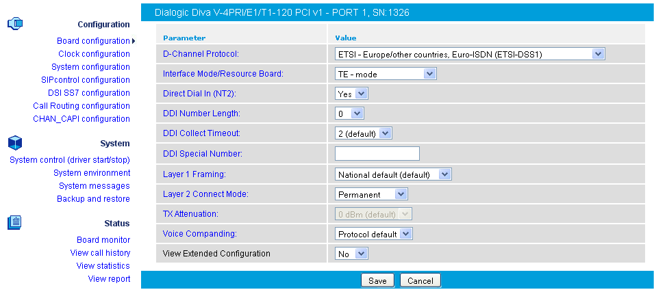
As soon as the configuration process is complete, click Save to update the Diva Media Board configuration. The Diva Media Board configuration utility tries to update the changed configuration parameters on demand, i.e., without a board restart. If the changed parameters cannot be updated in this way, the Dialogic® Diva® WEB server will ask you to restart the Diva Media Board.
This feature is only available on specific Dialogic® Diva® xBRI and V-xPRI Media Boards. Clock synchronization may be necessary, if one port of the Diva multiport Media Board is connected directly to the ISDN line and the other ports are connected to the PBX, so that the clocks of the ports may drift. With the clock synchronization, the ports configured as NT are synchronized with the TE ports on the same Diva Media Board.

To synchronize the ports, you have two options:
If you click System configuration on the left hand side, a page opens that allows you to configure global system parameters that affect the installed boards and device drivers, to optimize the configuration of your system, such as Fax-, RAS-, or Voice server, to select the applications and interface drivers to be loaded (CAPI, TTY), and to control misc. system services (accounting, etc.).
Note: The activation of the SIP-PSTN gateway (Dialogic® Diva® SIPcontrolTM software), the SIP enabled CAPI (Dialogic® Diva® softIP software), the DSI SS7 for Diva support (Dialogic® DSI SS7 for Diva® Media Boards), or specific features on the Dialogic® Diva® Media Boards require a valid license. See License activation for more information.

This page allows you to configure number ranges, different targets (CAPI/DSAPI vs. TTY), and different kinds of call distributions. You may configure the call routing for each controller. Note that if the first rule for a called party number matches, the remaining rules for the same number are ignored.
Note: If you select to configure the call routing, the parameter Direct Dial In (NT2) is automatically set to Yes.
To configure the call routing options:

The Dialogic® Diva® System Release is compatible with the CHAN_CAPI Asterisk interfaces. The CHAN_CAPI is a specific use case to provide CAPI-based ISDN hardware support. It establishes the connection between the PBX software and ISDN hardware, which provides a CAPI 2.0 compatible interface.
During the installation of the Diva System Release LIN software, the installation process detects automatically if Asterisk is installed and if the header files to build the CHAL_CAPI driver are available.
If Asterisk is installed, the user will be asked if the CHAN_CAPI driver should be build. After confirmation, the build process automatically detects the installed Asterisk version and creates and installs the required CHAN_CAPI driver.
If Asterisk is not installed, the documentation for using Asterisk with Diva is available in the web configuration. Asterisk may be installed or updated after the Diva System Release is installed. In this case, the build process for the Diva System Release can be started again and will create and install the CHAN_CAPI driver.
The CHAN_CAPI configuration generates a capi.conf Asterisk configuration file and modifies the modules.conf and makes the available options visible. You need to write your own extension.conf. Consult the examples in the internet for reference. For Diva-specific commands, see the README, README.media, README.Diva.fax, and README.Diva.qsig files.
Notes:
To open the online help for a specific parameter, click the parameter and a window with the help text will pop up.

If you click System control (driver start/stop) the following page opens, where you can start and stop Dialogic® Diva® drivers. The Dialogic® Diva® WEB server will detect the current state of the drivers and will open the appropriate page. Moreover, this page allows you to view the log file of the last driver start/stop configuration procedure.

Note for Dialogic® BlueTM Telephony Boards:
Dialogic® BlueTM Telephony Boards can be started in kernel mode or user mode. Normally, they are started in kernel mode. If the kernel mode fails, they are started in user mode. The Last operation log in the web interface will show you in which mode the driver was started. For more information see also, Verifying the operating mode of the Dialogic® Blue(TM) Telephony Boards.
You can also verify the modus under Board monitor of the web interface. To do so:
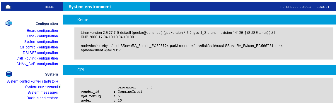
This page allows you to get important information about your system (kernel version, PCI hardware configuration, system resources, etc.). Most of the information is retrieved from the /proc file system.
This page allows you to view the last 200 messages from the kernel ring buffer. This is equivalent to the command dmesg > msg.txt && tail -n 200 msg.txt.

If you need to create a backup of your configuration, you can do so with the backup and restore functionality.
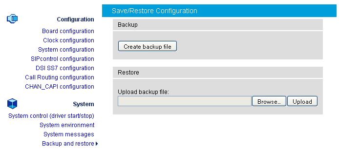
To create the backup file:
If you click Download backup file button, a window opens giving you the options to either open the file or to save the file. Choose one option and click OK.
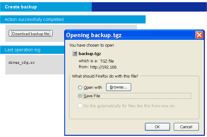
To restore the backup file:
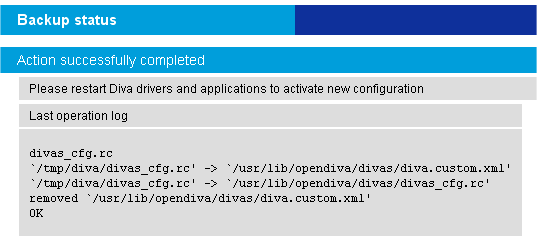
If you click Board monitor on the left hand side, the following page opens, which allows you to check the current status and the configuration of the installed Dialogic® Diva® Media Boards, to read internal board trace buffers (XLOG) and to gain access to the Management interface of Diva Media Boards and drivers:

You can navigate through the Management interface of the selected Dialogic® Diva® Media Board or driver using the management interface browser:

The management interface is available for:
If you click the icon below Mgnt in the Available Diva Board section, the management interface browser opens. The management interface browser allows you to navigate through the management interface directories, read, write, and execute management interface variables using the buttons under Operation.

If you click the icon below Mgnt for the CAPI driver in the Available System Release driver section, the management interface browser opens. The management interface browser allows you to navigate through the management interface directories, read, write, and execute management interface variables using the buttons under Operation.

If you click the icon below Mgnt for the TTY driver in the Available System Release driver section, the management interface browser opens. The management interface browser allows you to navigate through the management interface directories, read, write, and execute management interface variables using the buttons under Operation.

This page allows you to view the last segment (up to 10000 calls) of the call record that is stored in the /var/log/divalog file. This file contains the information about call time, duration, call parameters, e.g., calling/called party numbers, used protocol, transmission speed, remote fax station id, or fax features.
The record file of the call is stored in ASCII format and can be downloaded to a local machine. To receive more details on the format of the call record file, read about the"divalogd" accounting utility.
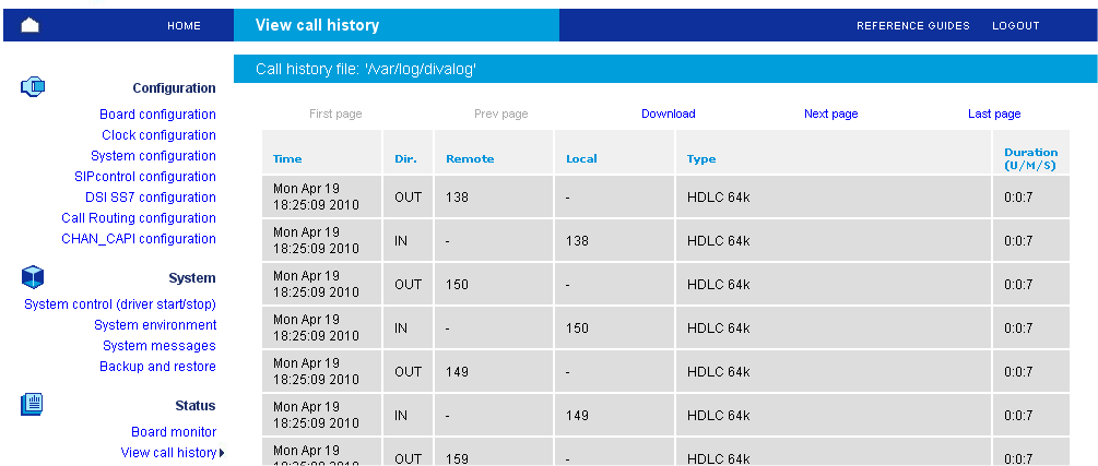
This page allows you to perform statistical analysis of the call record (call journal) files. The result of the analysis is presented as sequence of pie- and chart- diagrams (stored as JPEG files).
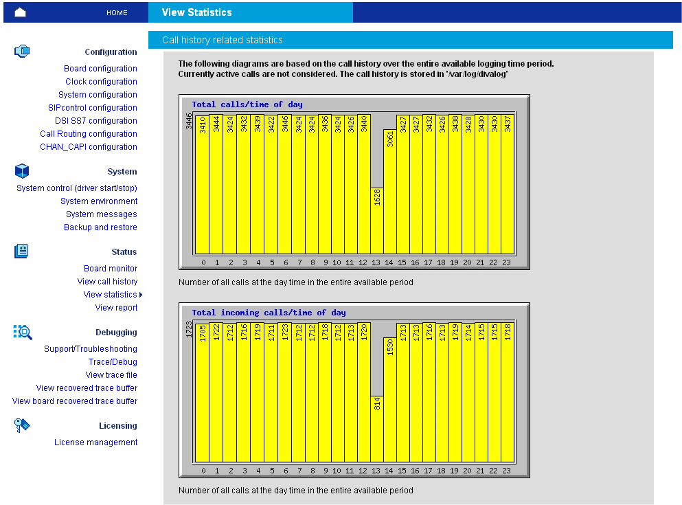
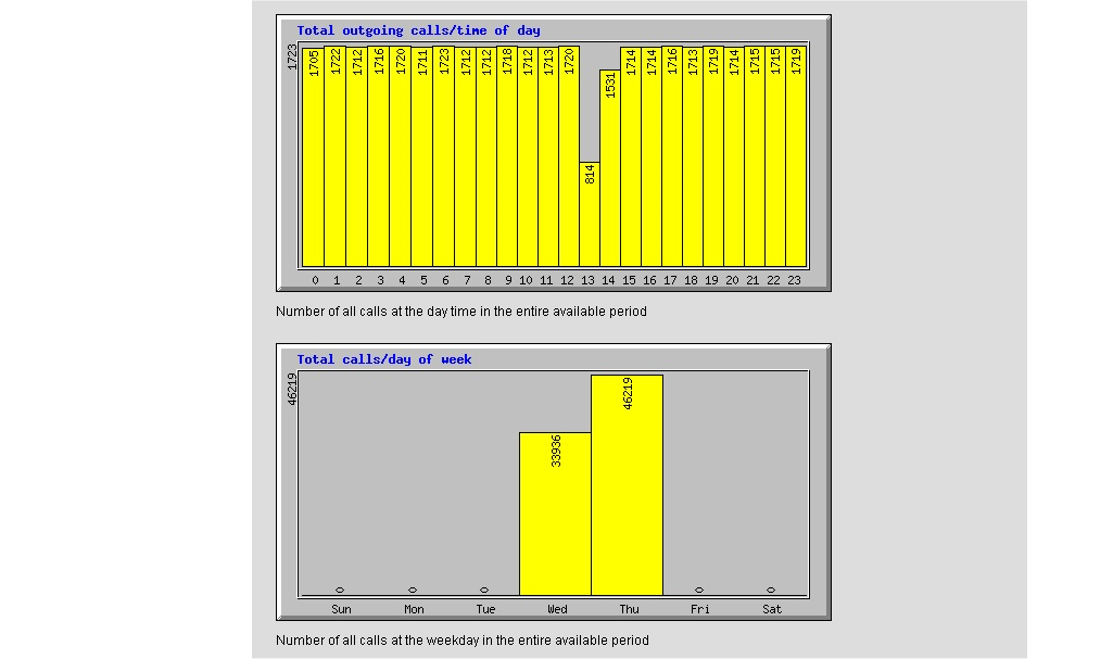
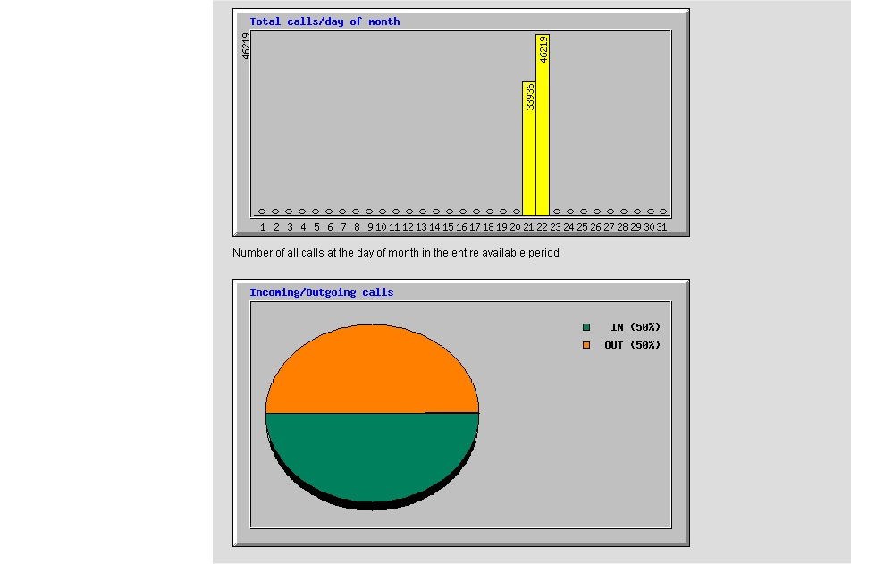
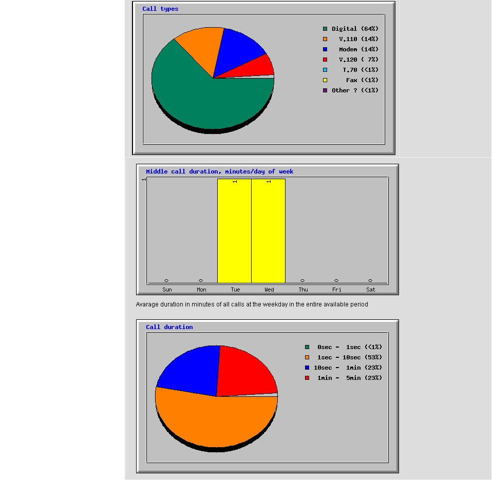
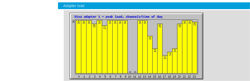
This page allows you to view the state and the cumulative statistics for the active Dialogic® Diva® Media Boards. If you click the board icon below Details, the information listed here is displayed. The information contained in the report originates from the management interface of the Diva Media Boards.
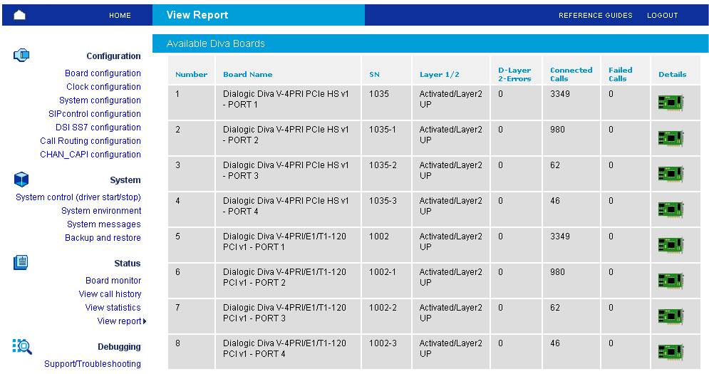
In case of a problem, you can use this page to capture relevant information for your support request:
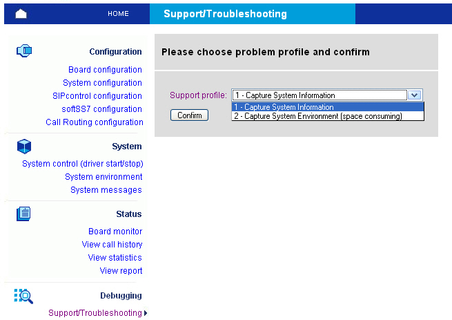
You can invoke the support procedure in two modes: The first mode captures the most important information about your system in one text file, whereas the second mode captures system environment information (kernel image, modules, configuration files) that allows the Dialogic Customer Support personnel to reproduce your environment locally. Finally, you can download the report file as compressed archive.
This page allows you to select the trace profile and level, to set trace ring buffer size and to activate the background trace process:
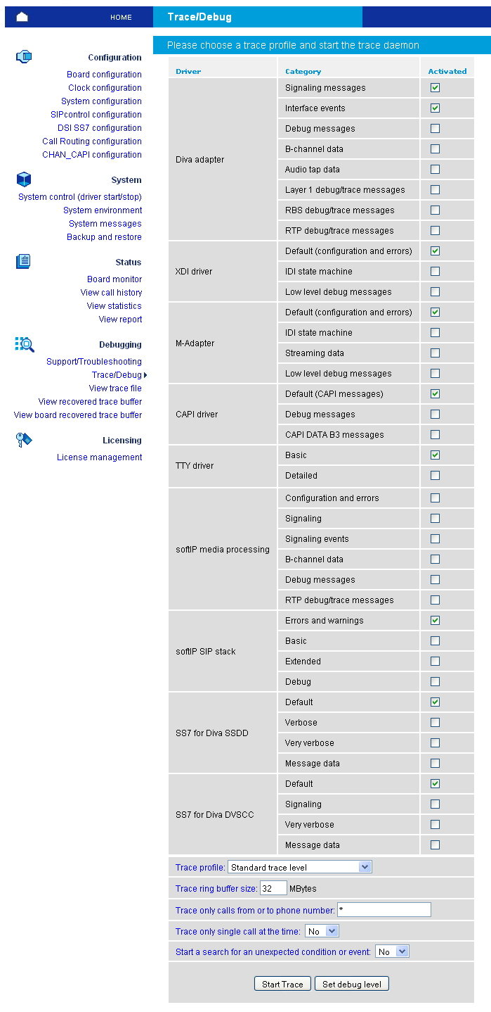
Once the trace process (ditrace) is running, you can issue one test call or stop the trace process and retrieve compressed trace file.
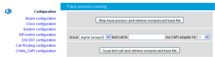
At any time, you can view the context of the trace ring buffer file (even if the trace process is still running) using the trace file viewer. See View trace file for more information.
This page allows you to decode and to view a trace file. You can filter the trace file to view only specific sources of information:

Finally, you can view or download the decoded trace file:

Orange and green trace messages deal with the call establishment.
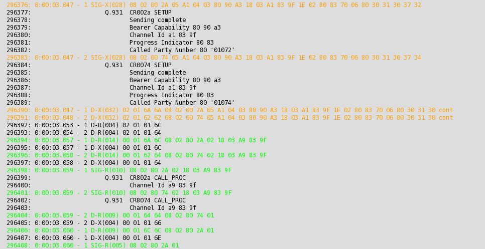
Red trace messages deal with the call release.
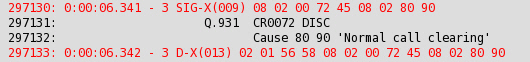
Some of the messages are displayed as HTML links (underlined). You can receive more information about messages if you activate the link:
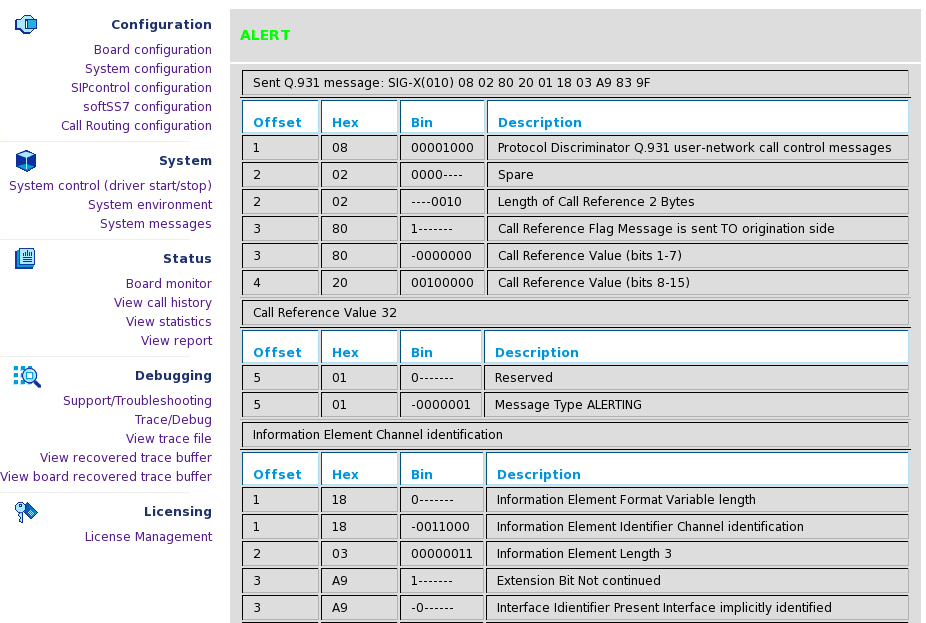
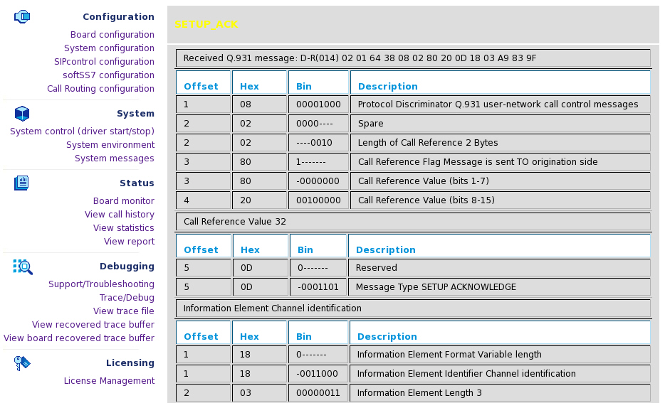
The blue trace messages (and HTML links) deal with AudioTap data. Audio taps are the audio data samples on the input (output) of the analog modem and fax DSP code combined with control information from the DSP code (events, EYE patterns). You can click the silver HTML link to start the Audio Tap Analyser that includes numerous tools.

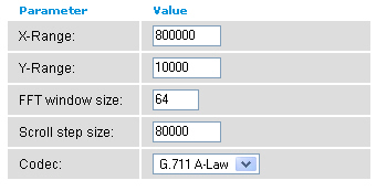
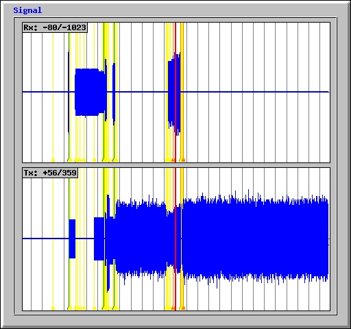
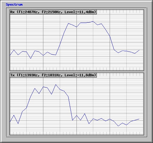
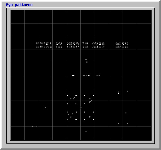
Moreover, it is possible to download an Audio Tap file in "WAV" file format.
This page allows you to view or download the decoded trace file.

The internal debug/trace buffer of Dialogic® Diva® MAINT driver is saved to /var/log/maint.bin file every time system was rebooted or received kernel panic at time Diva MAINT driver (diva_mnt) was loaded and at least one Dialogic® Diva® PRI Media Board was present in the system and was in the active state.
Each Dialogic® Diva® Media Board provides different features and capabilities with the Dialogic® Diva® System Release software. The table below outlines the feature set of the Diva Media Boards.
The services provided by the Dialogic® Diva® Media Boards are accessible via system interfaces. The features may not be available on every supported interface. The interfaces supported by Diva Media Boards are as follows:
Supported interfaces
Interface |
Description |
IDI (ISDN Direct Interface) |
Supports the features and capabilities of Dialogic® Diva® Media Boards. |
COM Port (TTY interface) |
For applications that require communication via a standard PC communication port. |
CAPI 2.0/Dialogic® Diva® API |
Common ISDN Application Programming Interface. A standard interface for applications to interact with Diva Media Boards. |
The features list of Dialogic® Diva® BRI and PRI Media Boards is divided in:
To view the Features of Dialogic® Diva® Analog Media Boards click this link.
The following features are available with the Diva ISDN Media Boards:
Feature |
IDI |
TTY |
CAPI 2.0 / |
Transparent HDLC, 64/56[d] kbps |
• |
• |
• |
Transparent (Voice) (8 bit 8 kHz A- Law/u-Law) |
• |
• |
• |
X.75 64/56[d] kbps |
• |
• |
• |
X.75/V.42bis |
• |
• |
• |
T.70/T.90 (T-Online) [g] |
• |
• |
• |
V.110 (GSM) [a] [g] |
• |
• |
• |
V.120 64/56 kbps (CompuServe) |
• |
• |
• |
V.120/V.42bis |
• |
• |
• |
Digital (Central Office) V.90 modem [a] |
• |
• |
• |
V.34+, V.90 analog modem [a] [d] [g] |
• |
• |
• |
SMS modem ETSI V1,V2 and auto-detection [a] |
• |
• |
• |
Dialogic® Diva® Fast Setup [a] |
• |
• |
• |
SDLC |
• |
• |
• |
V.42, V.42bis[a] [d] [g] |
• |
• |
• |
Change of B-channel protocol |
• |
|
• |
LAPD/B |
• |
|
• |
X.25 [e], X.31, ISO 8208 in the B-channel |
• |
|
• |
PIAFS 1.0, 2.0, and 2.1 [b] |
• |
• |
• |
Automatic call type and PPP frame type detection |
|
• |
|
Async/sync conversion |
|
• |
|
Fax Group 4 [c] [g] |
• |
|
• |
T.30 Fax Group 3 (analog) [a] [g] |
• |
• |
• |
FAX CLASS 1, 2 [a] [g] |
|
• |
|
Fax with Error Correction Mode (ECM) [a] [g] |
• |
• |
• |
Fax with MR (D2 coding) [a] [g] |
• |
• |
• |
Fax with MMR (T.6 coding) [a] [g] |
• |
• |
• |
Fax 33.6 kbps with MMR (T.6 coding) [a] [g] |
• |
• |
• |
Fax 14.4 kbps [a] [g] [h] |
• |
• |
• |
Fax 33.6 kbps (V.34) [a] [g] [h] |
• |
• |
• |
Fax T.38 (up to 33.6 kbps) [h] |
• |
• |
• |
Fax tone detection [a] |
• |
• |
• |
Reversal of fax direction [a] [g] |
• |
|
• |
Fax polling / fax on demand [a] [g] |
• |
• |
• |
Fax speed and feature indication (polling and ECM) [a] [g] |
• |
• |
• |
Fax SEP/SUB/PWD [a] |
• |
• |
• |
Fax NSF [a] |
• |
|
• |
New fax header line [a] [g] |
• |
|
• |
Page formats: ISO A4, ISO B4, ISO A3 [a] [g] |
• |
|
• |
Resolution: standard, fine, super-fine, ultra-fine [a] [g] |
• |
|
• |
DTMF tone detection and transmission [f] |
• |
|
• |
DTMF clamping [a] |
• |
|
• |
Cross-board switching (via line interconnect) |
• |
|
• |
Media mode (unknown, interactive voice, automated voice) |
• |
|
• |
Echo cancellation [a] [d] |
|
|
• |
Real time protocol (RTP) [a] [d] |
|
|
• |
Comfort noise generation (CNG) [a] [d] |
|
|
• |
Voice activity detection (VAD) [a] [d] |
|
|
• |
Dynamic anti-jitter buffer [a] [d] |
|
|
• |
VoIP processing [a] |
|
|
• |
Transparent D-channel |
• |
|
• |
X.25/D-channel including AO/DI support |
• |
|
• |
Notes:
[a] These features are not available with Dialogic® Diva® PRI/E1/T1-CTI Media Boards.
[b] PIAFS support is not available with Dialogic® Diva® BRI-2FX Media Boards.
[c] Including T.90/ISO8208 and module mode detection.
[d] These features are not available with the Dialogic® Diva® BRI-2FX Media Board.
[e] CAPI 2.0 (Dialogic® Diva® API) supports X.25 in the B- and D-channel, permanent virtual connections (PVC) and switched virtual connections (SVC), and multiple logical connections per B-channel.
[f] DTMF tone detection and transmission is done via soft DTMF for the Dialogic® Diva® PRI/E1/T1-CTI Media Boards.
[g] These features are not available with Dialogic® Diva® V-PRI Media Boards. For Dialogic® Diva® V-1PRI, V-2PRI, V-4PRI, and V-8PRI Media Boards, features are available via licenses.
[h] Dialogic® Diva® UM-Series Media Boards support fax up to V.34 on 50% of the available channels.
For an overview of supplementary services supported by the different switch types, see Supplementary services of Dialogic® Diva® BRI and PRI Media Boards per switch.
Supplementary Service |
IDI |
TTY |
CAPI 2.0 |
MSN (multiple subscriber number) |
• |
• |
• |
DDI (direct dialing-in) |
• |
• |
• |
SUB (sub-addressing) |
• |
• |
• |
CLIP (calling line identification presentation) |
• |
• |
• |
CLIR (calling line identification restriction) |
• |
|
• |
COLP (connected line identification presentation) |
• |
|
• |
COLR (connected line identification restriction) |
• |
|
• |
CCBS (call completion to busy subscriber) |
• |
|
• |
CCNR (call completion on no reply) |
• |
|
• |
KEY (keypad protocol) |
• |
|
• |
TP (terminal portability) |
• |
|
• |
Call forwarding unconditional |
• |
|
• |
Call forwarding busy |
• |
|
• |
Call forwarding no reply |
• |
|
• |
Call deflection |
• |
|
• |
CW (call waiting) |
• |
|
• |
HOLD (hold and retrieve a call) |
• |
|
• |
ECT (explicit call transfer) |
• |
|
• |
AoC (advice of charge) |
• |
|
• |
Three-party conference |
• |
|
• |
Large conference |
• |
|
• |
User-to-user signaling |
• |
|
• |
The Dialogic® Diva® System Release software supports basic call services for the available switch types. In addition to this, it offers supplementary services for the following switch types:
QSIG support is available for the derivatives ETSI-SS, ECMA-QSIG, and ETSI- QSIG. Thus, the QSIG switch type can be used with any PBX based on one of these derivatives. QSIG has been tested with a number of various switches, for example, Hicom 150, Hicom 300, Lucent Definity, Alcatel 4200, Alcatel 4400, Ericsson MD 110, Nortel Meridian, and Nortel M65xx.
The table below gives a detailed overview of the supplementary services supported by the switch types listed above. The availability of supplementary services also depends on your PBX. For detailed information on supplementary services supported by your PBX, contact the PBX manufacturer.
Supplementary Service |
Euro-ISDN (ETSI) PRI |
Euro-ISDN (ETSI) BRI |
QSIG |
5ESS Custom, 5ESS NI, DMS 100 |
MSN (multiple subscriber number) |
• |
• |
• |
• (incoming) |
DDI (direct dialing-in) |
• |
• |
• |
• |
SUB (sub-addressing) |
• |
• |
• |
• |
CLIP (calling line identification presentation) |
• |
• |
• |
• |
CLIR (calling line identification restriction) |
• |
• |
• |
• |
COLP (connected line identification presentation) |
• |
• |
• |
• |
COLR (connected line identification restriction) |
• |
• |
• |
• |
CCBS (call completion to busy subscriber) |
|
• |
• |
|
CCNR (call completion on no reply) |
|
• |
• |
|
KEY (keypad protocol) |
• |
• |
• [a] |
• |
TP (terminal portability) |
|
• |
|
• |
Call forwarding unconditional |
|
• |
|
|
Call forwarding busy |
|
• |
|
|
Call forwarding no reply |
|
• |
|
|
Call deflection |
|
• |
|
|
CW (call waiting) |
|
• |
|
• |
HOLD (hold and retrieve a call) |
• [b] |
• |
• [c] |
• |
ECT (explicit call transfer) |
|
• |
• [d] |
• |
Path replacement |
|
|
• |
|
Single-step call transfer (over CAPI deflection) |
|
|
• |
|
AoC (advice of charge) |
• |
• |
• |
|
Three-party conference |
|
• |
|
• |
Large conference |
|
• |
|
• |
Drop conference |
|
• |
|
• |
User-to-user signaling |
• |
• |
• |
|
Name identification services |
|
|
• [e] |
• [f] |
Generic functional procedures (basis for supplementary services in QSIG environment) |
|
|
• |
|
Common information |
|
|
• |
|
Redirected number translation from QSIG to Q.931 |
|
|
• |
|
Escape message types |
|
|
|
• [g] |
Call Appearance/Call Handling (CACH) plus configuration |
|
|
|
• |
Configurable feature activators |
|
|
|
• [h] |
Network display conversion/treatment |
|
|
|
• |
Message waiting |
• |
• |
• |
• |
Notes:
[a] In a QSIG environment, the feature is also called "Simple Dialog".
[b] HOLD is not a standard supplementary service for Euro-ISDN PRI, nevertheless some PBXs support call hold and retrieve.
[c] HOLD is not defined in QSIG but corresponding procedures are available.
[d] Call transfer is only possible if path replacement works for one sub-PBX.
[e] Presented by switch.
[f] Presented by the network.
[g] 5ESS custom only
[h] "5ESS NI" and DMS100 only
Dialogic® Diva® Analog Media Boards offer the following feature set:
The following features are available with Dialogic® BlueTM OneSpan-24/30-S-LP Telephony Boards:
* depends on host performance
If you need features not covered with your Dialogic® BlueTM Telephony Board, such as fax or modem, contact your Sales representative who can offer you the Dialogic® Diva® Media Board that will meet your needs.
Once the .bin files (binary files) are installed, the modules still have to be translated for the running kernel.
The following drivers are available as source code under GPL license:
They can be compiled for a specific kernel using the source level package.
Build procedure
To build base Dialogic® Diva® drivers, proceed as described below:
./Build.The Dialogic® Diva® TTY driver is provided only in binary form, and can only be recompiled for your own kernel using the source level package.
This section describes the usage of this driver with customized kernels if the aforementioned method is not applicable.
The Dialogic® Diva® TTY interface relies on a limited amount of exposed kernel services. If the appropriate services do not differ from the services the Dialogic® Diva® TTY driver was originally compiled for, then you can still use the driver with your customized kernel. Therefore, the Diva TTY driver for single processor machines is compiled without symbol version information and can be loaded in every kernel that exports the requested externals. If the driver cannot be loaded due to different kernel version/name, you can try the forced module load.
Notes:
insmod -f Divatty.o command.The Linux kernel is "monolithic". The interface between the kernel and the loadable kernel modules, especially the layout of internal kernel structures, can change depending on the current kernel configuration. It is clear that in case the kernel and the loadable kernel module have different layout of shared structures you can still load the module, but it can lead to instabilities or Oops.
Another cause for Oops and instabilities is the different processor model. The loadable kernel module which is optimized for PentiumPro CPU can cause problems if loaded in the kernel that was optimized for Pentium CPU.
In case your system becomes instable after the Diva TTY driver was loaded, you can follow the general rules described below. These rules allow you to create the customized kernel which will be compatible with the Diva TTY driver:
Note: You can use the command objdump -s Divatty.o > info1.txt; objdump - s vmlinux > info2.txt and view the context of the ".comment" sections.
nm -u Divatty.o command the list of TTY driver kernel services (functions) used by the Dialogic® Diva® System Release software.Note: You can receive detailed information about all exported data structures, functions and the structures on which the exported functions depend on if you activate the symbol version information, change the kernel Makefile from "genksyms" to "genksyms -D" and execute make modules 2>info.txt && grep Export info.txt > exports.txt.