 You must use the same API format (Basic or Extended) on all nodes on a single EXNET ring.
You are here: CSP Developer’s Guide: Overview > 10 Configuring Multi-Node Systems > Configuration

Purpose
This section describes how to bring an CSP into service. It assumes that all hardware configuration and cabling is complete, that all CSP nodes are powered-up, and that a communication link exists between the host and nodes.
Before you begin to configure an CSP, map out your configuration plan clearly, and record information on each node. See the Hardware Installation and Maintenance Guide for more information.
Important! Perform all configuration first, before bringing the system into service.
You must use the same API format (Basic or Extended) on all nodes on a single EXNET ring.
|
Step |
Action |
API Message |
|---|---|---|
|
1 |
Download System Software |
|
|
2 |
Re-establish Socket Connections |
|
|
3 |
Assign Logical Node IDs |
Assign Logical Node ID |
|
4 |
Configure Nodes |
EXS Node Configure |
|
5 |
Configure Ring |
EXNET Ring Configure |
|
6 |
Bring Ring In-Service |
Service State Configure |
The following steps detail the procedure for configuring your CSP as shown in the table above.
When an IP socket is opened to a node, the host begins to receive Poll messages indicating that the node requires a system software load. The Node ID field is 0xFF, indicating that a node ID has not yet been assigned. Download the system software to each node individually, following the procedure detailed in Application Development chapter.
Downloading the system software purges all local and distributed traffic. After the system software is downloaded, you must reconfigure all nodes and all EXNET rings. The host must verify that each node has received the new software load.
2. Re-establish Socket Connections
After each Matrix Controller resets, you must re-establish each Matrix Controller card’s socket connection. Each node then sends Poll and Node Status Report messages, indicating that the node requires a Logical Node ID, which you must assign. The Node Status Report message is sent only if a node is an CSP node. The software determines that a node is an CSP node by the presence of an EXNET-ONE card. So you must install the EXNET-ONE card before you power up the CSP. The CSP continues sending Node Status Report messages, about every five seconds, until a Logical Node ID is assigned.
Assign a Logical Node ID (0-31) to each node, using the Assign Logical Node ID message. All nodes on the same Ethernet segment must have a unique Logical Node ID and there must be one Logical Node ID for each Physical Node ID. If a node ID is already assigned, the Assign Logical Node ID message receives a negative acknowledgment (NACK).
Important! The Logical Node ID must be in the range of (0x00–0x1F).
The first node to be assigned a Logical Node ID becomes the master node of the EXNET ring, and it obtains transmit bandwidth on the ring. As subsequent nodes are assigned Logical Node IDs, they also obtain bandwidth on the ring.
If a message to a node is addressed with an incorrect Logical Node ID, the CSP responds with a status of "Invalid Logical Node ID." The Logical Node ID field in the header of the response indicates the correct Logical Node ID.
You can now configure each node the same way that you configure a stand-alone CSP, with the following considerations that are specific to the multi-node CSP:
Logical Span IDs
Logical Span IDs must be unique across all nodes in an CSP. If a duplicate ID is assigned, a response status of Logical Span ID Already Assigned is returned to the host. Each node keeps a record of every other node’s Logical Span ID.
ISDN PRI, DASS2, and SS7 PQ card resources are available and addressed to ports that reside in the same node as those cards. However, you can use a DSP resource on a single node for conference connections among multiple nodes. Other DSP resources can be used locally only. Please refer to DSP Resource Specifications for more information.
Use the EXNET Ring Configure message to perform the following tasks on each node:
1. Assign a Logical Ring ID.
2. Configure four packets to be transmitted.
3. Configure Ring Timing (See Expanding the EXNET Ring for more information).
4. Configure the Transmit/Receive mode of each ring on a node to Transmit and Receive. If you have a multi-ring configuration, please contact Excel Technical Support for assistance.
5. Configure CSP Conferencing, if required.
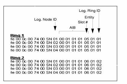
The following examples show a T1 configuration with four nodes and a redundant EXNET ring. The EXNET-ONE for Ring 1 is in Slot 5 and the EXNET-ONE for Ring 2 is in Slot 6.
You must send an EXNET Ring Configure message to the
EXNET-ONE card attached to each ring. You must assign the same Logical Ring ID to all EXNET-ONE cards on that ring.
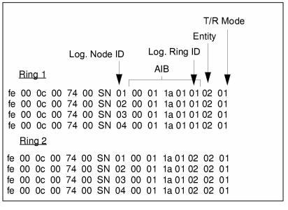
The sequence of messages shown in Assign Logical Ring ID is sent to assign Logical Ring ID 1 to the four nodes on the ring.
Figure 10-1 Assign Logical Ring ID
The following example shows details of the first message from the sequence below.
|
BYTE |
Field Description |
Value and Indication |
|---|---|---|
|
0 |
0xFE |
|
|
1, 2 |
0x000c |
|
|
3, 4 |
Message Type |
0x0074 (EXNET Ring Configure) |
|
5 |
Reserved |
0x00 |
|
6 |
Sequence Number |
0xSN |
|
7 |
Logical Node ID |
0x01 (Logical Node 1) |
|
8 |
Address Method |
0x00 (Single Entity) |
|
9 |
Number of Address Elements |
0x01 |
|
10 |
AIB Type |
0x01 (Slot) |
|
11 |
Address Data Length |
0x01 |
|
12 |
Address Data[0] Slot Number |
0x01 (Slot 5) |
|
13 |
Entity |
0x01 (Assign Logical Ring ID) |
|
14 |
Data[0] Logical Ring ID |
0x01 (Logical Ring 1) |
|
15 |
Checksum |
|
The sequence shown in Configure Number of Packets configures a node to transmit four packets.
Figure 10-2 Configure Number of Packets
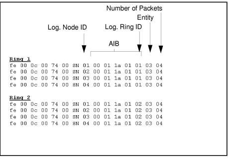
Table 10-1 Message Example
|
BYTE |
Field Description |
Value and Indication |
|---|---|---|
|
0 |
Frame |
0xfe |
|
1, 2 |
Length (MSB, LSB) |
0x000c |
|
3, 4 |
Message Type |
0x0074 (EXNET Ring Configure) |
|
5 |
Reserved |
0x00 |
|
6 |
Sequence Number |
0xSN |
|
7 |
Logical Node ID |
0x01 (Logical Node 1) |
|
8 |
AIB Address Method |
0x00 (Single Entity) |
|
9 |
Number of Address Elements |
0x01 |
|
10 |
AIB Type |
0x1A (Logical Ring) |
|
11 |
Address Data Length |
0x01 |
|
12 |
Address Data[0] Logical Ring ID |
0x01 (Logical Ring ID 1) |
|
13 |
Entity |
0x02 (Configure Number of Packets) |
|
14 |
Data[0] Number of Packets |
0x04 (4 Packets) |
|
15 |
Checksum |
|
Configure Transmit/Receive Mode
Configure the Transmit/Receive mode of each ring on a node to Transmit and Receive. If you have a multi-ring configuration, please contact Excel Technical Support for assistance.
Important! Before you change the Transmit/Receive mode, you must set the number of packets transmitted. The default is four.
The sequence shown below configures all nodes in the system for Transmit/Receive mode.
Figure 10-3 EXNET Ring Configure - Configure Transmit and Receive Mode