You are here: SwitchKit CSA User’s Guide > 5 Configuring VoIP Cards and Features > Configuring IP Network Interface Series 2
Configuring IP Network Interface Series 2

This procedure describes the configuration of the IP Network Interface Series 2 (IPN S2) card.
Before you begin
For offline configuration, you must have a node view window open in configuration mode. If you want to configure online, the LLC and SwitchManager must be running. For information on running LLC and SwitchManager refer to the SwitchKit documentation. You must have a node view window open in configuration mode. If you plan to use IP-based routing, See Configuring SIP and Configuring H.323 . Also see the Developer’s Guide: Internet Protocol, Chapter 8, Routing VoIP Calls.
Before you configure an IP Network Interface Series 2 card, you must locate your license file (license.cfg) which contains a license key. The license file is included on a floppy disk that is shipped with the CSP system software CD. Copy the file to your CSA folder. To install the license key, you must use the General Node Configuration dialog box. See General Node Configuration for the procedure on opening the license key.
Configuring the IP Network Interface Series 2 card
The following steps explain the IP Network Interface Series 2 card configuration.
1 From the node view, invoke the IP Network Interface Series 2 configuration dialog box by doing one of the following:
• Double-click the IP Network Interface Series 2 (IPN S2) card in the node view.
• Select the IPN S2 card in the node view. Go to the Configuration menu and select Card®VDAC/IPN S2 Configuration.
• Right-click on the IPN S2 card in the node view and select VDAC/IPN S2 Configuration from the menu.
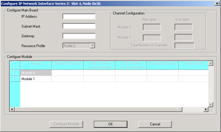
The Configure IP Network Interface Series 2... dialog box opens. See the next screen shot.
2 Enter the IP Address and Subnet Mask of the main board. After these values are entered and you tab to the next field, the Resource Profile field and module configuration become enabled.
Important! If you do not want internal routing tables to be created for this card, you must use the Configure PPL Tool dialog box to uncheck this option. See Specifying PPL Files. The internal routing tables that are enabled by default creates your IP-to-span-channel mapping that is installed on the CSP. Also, a separate config file is added to the SwitchManager file which is also shown in the Configure PPL Tool dialog box in Specifying PPL Files.
3 Enter Gateway, if applicable.
4 Select another Resource Profile, if you want to change the default value.
5 To assign all logical span IDs for the IP Network Interface Series 2 card, specify the Starting Span Number.
Important! The CSA provides default routing by mapping the specified spans with the IP Addresses of the IP Network Interface Series 2 modules.
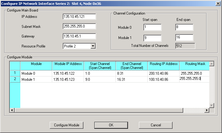
6 Specify the IP addresses for each Module in the Configure Module group. When you click out of the module IP address cell, the Start Span:Channel and End Span:Channel get populated automatically from having specified the Starting Span Number in the Channel Configuration group box.
7 If you are using IP-based routing, enter the Routing IP Address and Routing Mask of the endpoint that is within or outside the main board network.
These fields are enabled if you have done either of the following:
• Selected Enable Advanced IP Routing in the SIP configuration dialog box.
• Selected Enable Advanced IP Routing in the H.323 IP Signaling Series 3 card resource attributes configuration dialog box.
See the example data in the next screen shot.
8 Select the module you want to configure and click Configure Module. A dialog box opens to configure the IP Network Interface Series 2 card resource attributes for the selected module. The dialog box opens with default values. You can change the values, if required. The valid range of values for the fields, 2833 Dynamic Payload Type and 2198 Dynamic Payload Type, is 0-127. See the next screen shot.
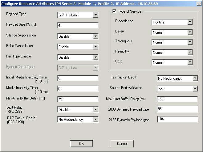
9 Click OK to close the Configure Resource Attributes IPN Series 2... dialog box.
10 Click OK to close the IP Network Interface Series 2 configuration dialog box. You may now configure the Channel Group and Range for the IP Network Interface Series 2 card. See Configuring VDAC-ONE and complete steps 9-17.
Important! Even though 512 channels (16 spans, 32 channels per span) can be configured on a single IP Network Interface Series 2 card, only 510 simultaneous calls are allowed when using the default VoIP module resource Profile 2. For VoIP resource Profile 2 on a IP Network Interface Series 2 card, one channel on each VoIP module is reserved for ICMP support.